P. S. Joshi1 and D. S. Sutrave2*
1Walchand Institute of Technology, Solapur University, Solapur, India,413006
2Department of Electronics, D.B.F Dayanand College of Arts and Science, Solapur University, Solapur, India,413002
Corresponding Author Email: sutravedattatray@gmail.com
DOI : http://dx.doi.org/10.13005/msri/130107
Article Publishing History
Article Received on : 18 May 2016
Article Accepted on : 01 Jun 2016
Article Published : 06 Jun 2016
Plagiarism Check: Yes
Article Metrics
ABSTRACT:
Ruthenium oxide, Manganese oxide and (Ru:Mn)O2 composite thin films have been prepared by 0.02M Ruthenium chloride and Manganese acetate solutions respectively on stainless steel substrates by sol-gel spin coating method. Layer by layer deposition of RuO2 and MnO2 was done for composite films. RuO2: MnO2 composite thin films have been demonstrated to be an excellent material for Supercapacitor application when evaluated with RuO2 and MnO2 thin film electrodes with respect to XRD, SEM, CV, CP and EIS studies. As a result, high specific capacitance of 515 F/g at 10 mV/s with excellent stability and long cycle life was obtained, where specific power and energy were as high as 15.38 Wh/kg and 4.06 KW/kg respectively with loading weight of 0.13 mg/cm2 .Composite films showed changes in structural and morphological features which was admiring for supercapacitor applications. The electrochemical impedance measurement was carried out in 0.1M KOH in the frequency range 10 to 105 Hz. From the analysis it can be concluded that mixed oxide composites have superior capacitive performance to single transition metal oxides as electrodes.
KEYWORDS:
(Ru:Mn)O2 composite thin films; Sol-gel; Cyclic voltammetry; Chronopotentiometry; Electrochemical Impedance Spectroscopy
Copy the following to cite this article:
Joshi P. S, Sutrave D. S. Study Of Ruthenium Oxide, Manganese Oxide and Composite (Ru:Mn)O2 Thin Film Electrodes Assembled by Layer by Layer Spin Coating Method. Mat.Sci.Res.India;13(1)
|
Copy the following to cite this URL:
Joshi P. S, Sutrave D. S. Study of Ruthenium oxide, Manganese oxide and composite (Ru:Mn)O2 thin film electrodes assembled by layer by layer spin coating method. Mat.Sci.Res.India;13(1). Available from: http://www.materialsciencejournal.org/?p=3893
|
Introduction
The development of energy storage devices is extremely important to store the harvested energy for wide applications. Batteries, conventional capacitors and supercapacitors are the commonly used energy storage devices. Nowadays, supercapacitors are exhibiting wide applications in electric vehicles, consumer electronic devices, pacemakers and so on. Supercapacitor offers the ability to store or release energy in timescales of a few seconds with extended cycle life.1-2 A number of transition metal oxides with various oxidation states represent a type of attractive materials for supercapacitors owing to outstanding structural flexibility and high specific capacitance. The major drawback is the high cost due to limited availability of ruthenium. With an aim to lower cost while improving the utilization, composite materials have been prepared by combining ruthenium oxide with cheap metal oxides, such as MnO2. Manganese oxide has been considered a very promising electrode material for supercapacitors because of low price, natural profusion along with good electrochemical behavior and environmental compatibility.3 The aim of this work is to develop Ruthenium oxide and Manganese oxide composite thin films for application in advanced supercapacitors by utilizing the cost as well as quantity of Ruthenium with a cost-effective sol-gel spin coating deposition technique.
Experimental
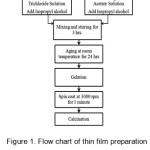
All solutions were prepared by using Analytical grade chemicals and Double distilled water. Firstly, 0.02M Ruthenium trichloride solution was prepared in double distilled water. Isopropyl alcohol was added then the solution was continuously and thoroughly stirred for 3 hours by magnetic stirrer. The gel was formed after aging the solution for 24 hrs. at room temperature. A stainless steel substrate having grade of 304 was used for deposition. After polishing by zero grade polish paper, (2cm X 2cm) strips were cut out of the sheet. A proper cleaning of the substrates was done. After that deposition was taken on cleaned SS substrates in spin coater unit at a speed of 3000 rpm. Then after calcinations at 900°C , uniform thin films of RuO2 were formed. The procedure was repeated for multiple coats. Same procedure was repeated by using 0.02 M Mn Acetate solution for deposition of MnO2 . Layer-by layer spin deposition is done for deposition of composite (Ru:Mn)O2 thin films. First two layers of RuO2 and then two layers of MnO2 were deposited. All the films studied here are of 4 coats. The schematic presentation of the procedure is given in figure 1.
Figure 1: Flow chart of thin film preparation by the sol–gel spin coat route.
The films were weighed before and after deposition. The electrodes were weighed by Contech Analytical electronic balance having 0.1mg sensitivity. Morphology of the RuO2 films of SS substrates was examined by SEM JEOLJSM 6360 and XRD was recorded using a X-ray diffractometer D2 PHASER using CuKa radiation (λ= 1.54 A°).As deposited films were used as electrodes so cyclic voltammetry and chronopotentiometry, EIS analysis were done by a electrochemical workstation CH Instruments CH1608E.
The area of 1 cm2 at an end of the strip was open in the electrolyte and the remaining was used as current collector. 0.1 M KOH electrolyte solution was used for electrochemical characterization of RuO2/SS electrodes and a three – electrode cell employing Pt auxiliary electrode and a saturated Calomel electrode as reference electrode.
Results and discussions
Structural Properties
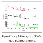
The X-ray Diffractogram of as deposited MnO2, RuO2, (Ru:Mn)O2 thin films is shown in Fig. 2.
Figure 2: X-ray Diffractogram of MnO2, RuO2, (Ru:Mn)O2 thin films.
The experimental data showed that tetragonal structure of RuO2 film (JCPDS Card No.-88-0322) with lattice constants of a=b=4.51 A°, c= 3.05A° .The d-values are equal to 2.20 A° and 1.68 A° corresponding to Miller Indices [111] and [211] respectively which are nearly same when compared with JCPDS card. Similarly orthorhombic structure of MnO2 film (JCPDS Card No.-82-2169) with lattice constants a=9.31A°, b=4.67A°,c=2.78A°. The d-values corresponding to Miller indices [410],[401],[520] are 2.06 A°,1.78 A°,1.43A°respectively. For (Ru: Mn)O2 films, the peaks for MnO2 as well as RuO2 has been observed but with decreased intensity. Also for composite films it was observed that there is a shift in angle 2θ for every peak. Intensity change is related to adsorption on surface while change in theta indicates inter-layer change [4].Usually on doping, the peak intensity decreases which might be due the change in electron density or might be due to point defects. Very small crystalline size or semicrystalline particles were signified by the broadness of the peaks [5]. The details are given in Table 1.
Table 1: 2θ and d-value variation for MnO2, RuO2, (Ru:Mn)O2 thin films
|
|
|
MnO2
|
Composite (Ru:Mn)O2
|
|
Peak no.
|
Plane
|
2θ
|
d
|
2θ
|
d
|
|
1
|
[410]
|
43.71
|
2.06
|
43.28
|
2.08
|
|
2
|
[401]
|
51.09
|
1.79
|
49.38
|
1.84
|
|
3
|
[520]
|
64.86
|
1.43
|
63.73
|
1.45
|
| |
|
RuO2
|
Composite (Ru:Mn)O2
|
|
5
|
[111]
|
40.92
|
2.20
|
40.57
|
2.22
|
|
6
|
[211]
|
54.49
|
1.68
|
53.92
|
1.69
|
Shift of Bragg peaks to lower values of the diffraction angle, increases lattice parameter. From Table 2. similar changes are observed. The table gives the comparison of lattice parameters for MnO2 , RuO2 and the composite films.
Table 1: 2θ and d-value variation for MnO2, RuO2, (Ru:Mn)O2 thin films
|
Lattice constants (A°)
|
Thin Films
|
|
a
|
b
|
c
|
|
|
9.31
|
4.51
|
2.79
|
MnO2
|
|
9.34
|
4.67
|
3.00
|
(Ru:Mn)O2
|
|
4.51
|
4.51
|
3.05
|
RuO2
|
|
4.57
|
4.57
|
3.03
|
(Ru:Mn)O2
|
Morphological Properties
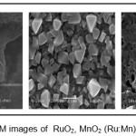
As the electrochemical performance of electrodes is strongly influenced by particle size, microstructure and porosity, the films were studied by SEM. The RuO2 thin films showed porous, mud-cracked morphology giving rise to high surface roughness .The MnO2 films showed non-uniformly distributed well developed grains with porosity. Interconnected web-like formation with porous void cavities was observed for (Ru:Mn)O2 composite film [6]. The porosity of the thin film prompts possibility of better electrochemical supercapacitor behaviour of the above discussed thin film electrodes.
Figure 3: SEM images of RuO2, MnO2 (Ru:Mn)O2 thin films
Electrochemical Properties
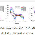
The electrochemical characterization of materials is often carried out using chronopotentiometry, cyclic voltammetry and EIS studies. The cyclic voltammetry graphs of specific capacitance versus scan rates is as shown in Fig.4.
Figure 4: Cyclic Voltammogram for MnO2 , RuO2, (Ru:Mn)O2 thin film electrodes at different scan rates.
The curves showing characteristic peaks in the given voltage ranges showed the pseudocapacitive activities and are different from the rectangular shape of ideal capacitors. The SC decreased from 172 to 45 F/g , 310- 140 F/g and 515- 245 F/g with increase in scan rate for MnO2, RuO2 and (Ru:Mn)O2 electrodes respectively. When the scan rate is low as the inner active sites undergo the redox transitions totally hence specific capacitance is produced and at high scan rate due to the diffusion effect of proton within the electrode. It can also be seen from CV that voltage window is not reliant on scan rate. The voltage window increases as which clearly indicates that the presence of MnO2 layer increases the voltage window of RuO2 electrode. Increased voltage window leads to improve the specific energy and power of the thin film electrode. 7 Figure 5. shows the variation of current with respect to voltage for the respective films at 10 mV/Sec scan rate.
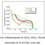
Figure 5: Cyclic Voltammogram for RuO2, MnO2, (Ru:Mn)O2 thin film electrodes at 10 mV/Sec scan rate.
The current under the curve is considerably higher for (Ru:Mn)O2 than for the RuO2 and MnO2 electrodes. Relatively high capacitance of (Ru:Mn)O2 thin film can be attributed to the porous structure which determined the ability of electrolyte ions to enter and to allow local ion transfer process. This indicates the superiority of (Ru:Mn)O2 as a potential electrode for supercapacitors.
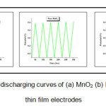
The charge storage properties and stability of the electrodes is studied by chronopotentiometry.Fig.6 shows the Charge/discharge sketch of RuO2, MnO2 and (Ru:MnO2) electrodes at 0.001 A/g of constant discharge current density. All the electrodes show nearly triangular shape indicating linear variation of the voltage linear variation of the potential through charging and discharging processes. Coulombic efficiency, power density and energy density are calculated by selecting a common voltage window for all the electrodes.
Figure 6: Charging-discharging curves of (a) MnO2 (b) RuO2 (c) (Ru:Mn)O2 thin film electrodes
Table 3 shows the variation of coulombic efficiency, power density and energy density of MnO2, RuO2 and (Ru: Mn)O2 thin film electrodes respectively. It could be seen that the performance of composite film had been increased than individual oxide thin film.
Table 3: Energy density, Power density and coulombic efficiency for MnO2, RuO2, (Ru:Mn)O2 thin film electrodes.
|
Thin Film Electrode
|
Energy density (Wh/Kg)
|
Power density (KW/Kg)
|
Coulombic efficiency(%)
|
|
MnO2
|
1.66
|
10.00
|
150
|
|
RuO2
|
2.22
|
10.00
|
133
|
|
(Ru:Mn)O2
|
4.06
|
15.38
|
95
|
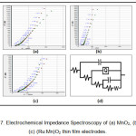
Mass and charge transfer process that take place at the interface of electrode/electrolyte and in electrode can be obtained by EIS. The Nyquist plots were plotted using frequency from 10- 105 Hz in 0.1 M KOH electrolyte for MnO2, RuO2 and (Ru:Mn)O2 composite thin films shown in figure 7.
Figure 7: Electrochemical Impedance Spectroscopy of (a) MnO2, (b)RuO2 (c) (Ru:Mn)O2 thin film electrodes.
The complex plane plot is divided into high and low frequency regions. The left intercept of Z” at Z’ axis corresponds to the series resistance Rs of the electrolyte in contact with the current collector and electrode. The right intercept of Z” at the Z’ axis represents parallel resistance Rp giving internal resistance of the electrode. The diameter of the semicircle represents ESR value. The value of power density increases with decrease in faradaic resistance.8 The plot through 45° phase angle corresponds to the Warburg impedance and it points to a high ion diffusion resistance. A straight line sharply increasing at the low-frequency region represents the dominance of capacitive behaviour. The initiation point of the line corresponds to knee frequency fk and its corresponding resistance Rk is given by Z’k. The values of Rs, Rp, ESR, fk, Rk are detailed in table 4.
Table 4: The values of Rs, Rp, ESR, fk, Rk for MnO2, RuO2and (Ru:Mn)O2 composite thin film electrodes.
|
Rs(Ω)
|
Rp(Ω)
|
ESR(Ω)
|
fk(Hz)
|
Rk(Ω)
|
Thin film Electrodes
|
|
14
|
17
|
3
|
55
|
3.83
|
MnO2
|
|
21.5
|
24
|
2.5
|
85
|
2.61
|
RuO2
|
|
9.2
|
11.2
|
2
|
34
|
3.09
|
(Ru:Mn)O2
|
Good agreement of simulated ( indicated by green color in figure7) and measured data ( indicated by red color in figure7) was found for the comparable circuit to the proposed one for individual as well as composite thin film electrodes. The proposed equivalent circuit is given in figure 7(d). Conway and Pell described the impedance of porous electrode using 5 element (n=5) circuit.9 C elements represent double layer capacitance and pseudo capacitance whereas R elements represent electrolyte resistance in pores, Faradaic resistance and equivalent series resistance of the electrodes. 10 The Constant Phase Element (CPE) or Q-element describes a leaking capacitor with microscopic roughness of the surface and capacitive dispersion of interfacial origin. EIS data gives the low value of ESR for the composite film than individual oxide thin film. Moderately low resistance is advantageous for high power supercapacitors.
Conclusion
Crystalline and highly porous (Ru: Mn)O2 composite thin films were prepared by sol-gel spin coating technique. The composite films showed admiring changes in structural and morphological properties for composite films as compared with single metal oxide thin film. Electrochemical analysis showed the maximum capacitance of 515 F/g, high power density of 15.38KW/Kg, high energy density of 4 Wh/kg and for composite film. The measured EIS data is in good agreement with calculated EIS data.
Acknowledgement
The Authors wish to acknowledge the U.G.C, New Delhi for financial support through the Major Research Project F No. 42-123/2013(SR).
References
- Rolison D. R., Nazar L. F. Electrochemical energy storage to power 21 st century. MRS Bulletin. 2011;36(07):486-493.
CrossRef
- Zhang L. L., Zhao X. S. Carbon based materials as supercapacitor electrodes. Chem.Soc.Rev. 2009;38(9):2520-2531.
CrossRef
- Devaraj S., Munichandraiah N. High capacitance of electrodeposited MnO2 by the effect of a surface-active agent. Electrochemical and solid state letters. 2005;8:373.
CrossRef
- Channua V. S. R., Williamsb L. Q., Kallurub R. R. Characterization of (Ru-Sn)O2 nanomaterials for Supercapacitors. Materials Sciences and Applications. 2011;2:1175-1179 doi:10.4236/msa.2011.29158 Published Online September 2011.
CrossRef
- Zhu J., Lu Z., Aruna S. T., Aurbach D and Gedanken A. Sonochemical Synthesis of SnO2 Nanoparticles and Their Preliminary Study as Li Insertion Electrodes. Chemistry of Materials. 2000;12(9):2557- 2566. doi:10.1021/cm990683l
CrossRef
- Bandgar D. K., Khuspe G. D., Pawar R. C., Lee C. S., Patil V. B. Appl. Nanosci. 2014;4:27–36.
CrossRef
- Kharade P. M., Chavan S. G., Salunkhe D. J., Joshi P. B., Mane S. M., Kulkarni S. B. Synthesis and characterization of PANI/MnO2 bi-layered electrode and its electrochemical supercapacitor properties. Materials Research Bulletin. 2014;52:37–41.
CrossRef
- Wang Y. G., Wang Z. D., Xia Y. Y. Electrochim. Acta. 2005;50:5641.
CrossRef
- Conway B. E., Pell W. G. Power limitations of supercapacitor operation associated with resistance and capacitance distribution in porous electrode devices. Journal of power sources. 2002;105:169.
CrossRef
- Kotz R., Carlen M. Principles and applications of electrochemical capacitors . Electrochimica Acta. 2000;45:2483.
CrossRef

This work is licensed under a Creative Commons Attribution 4.0 International License.