Evaluation and Characterization of Tensile Properties of Short Coated Carbon Fiber Reinforced Aluminium 7075 Alloy Metal Matrix Composites via Liquid Stir Casting Method
Suhas1,3, Jaimon D. Quadros2 and N. L. Vaishak1
1, 3Dept of Mechanical Engineering, Sahyadri College of Engineering and Management, Mangalore- 575007, India
2Dept of Mechanical Engineering, Birla Institute of Technology, Offshore Campus, Ras-Al-Khaimah, UAE
Corresponding Author Email: jaimonq@gmail.com
DOI : http://dx.doi.org/10.13005/msri/130202
Article Publishing History
Article Received on : 29-Sep-2016
Article Accepted on : 09-Nov-2016
Article Published : 16 Dec 2016
Plagiarism Check: Yes
Article Metrics
ABSTRACT:
The interface between the reinforcement and the matrix has a significant role in enhancing the property of the composite. In this work to increase the wetting ability of the reinforcement, nickel coating is done over the carbon fiber. The process of coating is carried out through three stages. It involves sensitization time, activation time and metallization time. Using the optimized time interval of the above process coating is done, on the fiber of range 0.6 to 1 micrometer. This coated fiber has the good cohesive property within each other, which increases the wettability. Stir casting process is carried out with the stirring speed of 200 rpm and the melting temperature about 780-8000C is used for the manufacturing of the composite. The results of this study revealed that, as the short coated carbon content was increased, there were significant increases in the Ultimate Tensile Strength (UTS). Furthermore, Scanning Electron Microscopy (SEM) was used in order to coordinate relationships between quality of the carbon fiber and aluminium alloy bond and thereby link with tensile properties of the metal matrix composites. The metal matrix composites are a very important role in the industries such as aerospace, automobile and sports equipment etc. The aluminium material is considered to be a light weight metal, to enhance the property of the aluminium 7075 alloy, the short coated carbon fibers added to the aluminium as a reinforcement.
KEYWORDS:
Aluminium 7075 Alloy; Carbon Fibers; Metal Matrix Composites; Stir Casting; Ultimate Tensile Strength
Copy the following to cite this article:
Suhas, Quadros J. D, Vaishak N. L. Evaluation and Characterization of Tensile Properties of Short Coated Carbon Fiber Reinforced Aluminium7075 AlloyMetal Matrix Composites via Liquid Stir Casting Method. Mat.Sci.Res.India;13(2)
|
Copy the following to cite this URL:
Suhas, Quadros J. D, Vaishak N. L. Evaluation and Characterization of Tensile Properties of Short Coated Carbon Fiber Reinforced Aluminium7075 AlloyMetal Matrix Composites via Liquid Stir Casting Method. Mat.Sci.Res.India;13(2). Available from: http://www.materialsciencejournal.org/?p=4531
|
Introduction
Metal Matrix Composites (MMCs) like most composite materials, provide significantly enhanced properties over conventional monolithic materials, such as higher strength, stiffness, and weight savings.1,2 Metal matrix composites are used in a wide range of high performance applications today. The MMCs have been used in over 5.5 million kg during the year 2006 and are finding impetus in annual growth rate of over 8%.3 The foremost applications include aviation, ground transportation, electronics and sports industries. Additionally, the applications also find themselves established in aeronautics with problems concerned to aero-structural, aero-propulsion and subsystem categories. Aluminum composites are very appealing because of their low thickness, their ability to be fortified by precipitation; their great corrosion resistance, high thermal and electrical conductivity, and their high damping limit.4 The strong demand for weight reduction in car and aircraft fabrication urges the optimization of the design of products employing low weight materials.5 The substitution of ordinary materials by lighter metals, for example, Aluminum alloys is, in this manner, exceedingly attractive. Notwithstanding, Aluminum alloys are not adequately solid or solid for some reasons and their reinforcement is important. Aluminum based MMCs are remarkable contender for these applications inferable from the high ductility of the matrix and the high quality of the hard reinforcing stages. The fascination for such materials is likewise because of the high modulus, quality to weight proportion, fatigue strength and wear resistance.6-7 The presence of reinforcing particles produces potential properties non-attainable by other materials.8 The reinforcement metal matrix offer potential for improvement in efficiency, mechanical performance and reliability over the new generation alloys.9-10 The presentation of a ceramic material into a metal framework delivers a composite material that outcomes in an alluring mix of physical and mechanical properties which can’t be acquired with solid combinations. There is an expanding requirement for information about the preparing systems and mechanical conduct of fiber reinforced MMCs in perspective of their rising generation volumes and their more extensive business applications. Composites have been developed with greater success by the use of fiber reinforcements in metallic materials.11 Earlier study on MMCs addressed the behavior of continuous fiber reinforcement composite based on aluminum, zinc and titanium alloys matrices and the reinforcements used was Alumina fibers, carbon fiber, glass fiber etc. The required literature has been studied in the field of Metal matrix composites (MMC) for thoroughly understanding the research involved. This literature survey provides brief ideas about the developments in MMCs. The survey has been made for the different methods on the reinforcements and also the different testing procedures for the improvement of the mechanical property, and also improved strength over the weight reduction. The literature survey was also made for different techniques available for electro less copper coating of the carbon fibers which is reinforcement for Aluminium. Ramnat et al.12 has provided a review on different techniques used for manufacturing Metal matrix composites. The Al alloys such as 6061, A356, 7075-T6 etc., and the reinforcing material such as Boron, SiC, Al2O3 etc. The process was carried by squeeze casting and powder metallurgy. Similarly Raviteja et al.13 carried out fabrication process and studied mechanical property of Al-Si2Cu/B4C composite. The composite preparation was carried out in stir casting technique using B4C as reinforcement added on to the matrix with the wt. % of 2, 4, 6, 8 and 10. The result has shown B4C particles have distributed homogeneously over the matrix. The mechanical tests like hardness and tensile revealed that, as the percentage of reinforcement increases in the matrix, hardness and tensile improved by 6.97% and 33% respectively when it is compared with as cast. Himanshu et al.14 have successfully prepared a particle reinforced metal matrix using aluminium as the matrix material and it is fabricated through stir casting method. Added particles are such as Alumina, B4C, and SiC etc., Particles in aluminium improves the hardness, yield strength, tensile strength while ductility is decreased. Addition of graphite in aluminium increases the tensile strength and elastic modulus but hardness is decreased. Also it shows a decrease in friction coefficient in case of Tribological behaviour. Zhongcai et al. 15 have studied the connection between the Cu for the electro less coating and the time and temperature of the bath solution. The work was also studied on the different quality of the carbon fibers under different bath condition. The scattering of the carbon fibers using the surfactant agents were discussed in this paper. Further Bhav et al.16 has performed an electro less copper coating on carbon fibers. The main intention behind the coating process was to avoid the interfacial reaction between the matrix and the reinforcement. Diameter of the carbon fiber which was used for the process of 6 micrometer and length 4-8mm were dipped into the different solutions for the different time and temperature and maintaining the pH between 10 and 13.Hajjari et al. 17 has studied the significant effect of tensile strength in Continuous Carbon Fibers Reinforces Aluminium Matrix Composites (CCFRAMCs).Electro less nickel coating of the Continuous CF has improved the wettability of the reinforcement. The carbon fibers coated with 0.5µm thickness of nickel layer by electro less coated with Al 2024 alloy as matrix. Investigation of the nature of fiber matrix interfaces existing in Al/C composites depending upon the presence of a nickel interlayer deposited on the carbon fibers and on the composition of the aluminium matrix was conducted by Silvain et al. 18 Results showed that the presence of this nickel layer eliminates the formation of aluminium carbide which is known to lower the mechanical properties of Al/C composites. Finally Zhang et al.19 investigated the variation of Tribological behaviour of the metal matrix composite due to the fiber length of short coated carbon fiber as a reinforcement which is dispersed in the epoxy. They found that the composite with longer short carbon fiber showed good result in wear resistance than the shorter short carbon fiber. And this study was done in the presence of graphite flake and TiO2 nano particles.
Based on the literature cited above, the objective of this work is to study the mechanical behaviour of Aluminium 7075 alloy /short coated carbon fiber composite, like ultimate tensile strength, hardness, compression strength, ductility using universal testing machine; to carry out the micro structural study of worn out surfaces of the composite material through the optical microscopy.
Materials and Methods
Preparation of Chopped Carbon Fibers
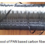
The PAN based continuous carbon fibers long strands which are winded in the spool as shown in the Fig.1.The continuous carbon fibers has to be cut to smaller length of 1mm.
Figure 1: Spool of PAN based carbon fibers.
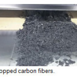
Figure 2: Chopped carbon fibers.
The continuous carbon fibers are separated from the spool and cut to length of approximately 30cm and placed on the manual printing press cutting machine. A manual feed of 1mm and less is given to machine for the cutting of carbon fibers as shown in Fig. 2.
The short carbon fibers are initially cleaned with acetone solution for 10 minutes, so that the carbon fibers maintain the proper roughness on the surfaces. The carbon fibers are then placed on the hot oven and preheated to 2000C, thus the acetone solution is evaporated and fibers are dried. The coating process involves 3 different stages such as i) Sensitization stage (S): In this stage the carbon fibers are dipped in a solution of 12grms/litre of SnCl2. 2H2O, they are sensitized for 15mins under continuous stirring. The carbon fibers are dried using filter paper and dipped in the 40ml/litre solution HCl for 5 minutes; ii) Activation stage (A): in this stage first the fibers are washed with distilled water and then they are exposed to the aqueous solution of 0.5 grams/litre of PdCl2 with continuous agitation. This process leads to formation of the Pd sites on the surface of the carbon fiber, which will further help in the metallization, iii) Metallization stage (M): The process of metallization starts with the heating the activated carbon fibers on the hot oven at 150o C for 20 minutes to eliminate the pyrolitic coating around the received fibers. The metallization solution is made by mixture of solution such as 10 grams/litre of NiSO4. 2H2O, 16 ml/litre of HCHO, 45 grams/litre of C10H16N2O8. The pH is maintained with 11 to 13 by adding NaOH pellets onto the solution. This stage is carried out with constant agitation at 80oC.
The process of coating preparation is carried out in a sequential manner. When the electro less coating is completed the coated carbon fibers are gets attached to each other which results in decrease in wettability of nickel coated carbon fibers on the aluminium metal matrix composites. For the separation of these nickel coated fibers without affecting the coating of the surface, the fibers are immersed in the solution of 20grams/litre solution of Sodium dodecyl sulphate (NaCL2H2SO4). Surfactants improves the dispersion ability of the carbon fibers in the aqueous solution and dispersion ability of the sodium dodecyl sulphate is good compare to other solutions such as polyethylene glycol or dodecyl benzene sulphonic acid. The fibers are dipped in the solution for 5 days for the proper scattering to take place. The optimized coating for prescribed sensitization, activation and metallization is selected from Table 1.
Table 1: Mean thickness of nickel coating on carbon fiber.
|
Trial no
|
S time (min)
|
A time (min)
|
M Time
(min)
|
Mean thickness
(µm)
|
|
1
|
5
|
5
|
1
|
0.7546
|
|
2
|
5
|
10
|
2
|
0.7680
|
|
3
|
5
|
15
|
3
|
0.6400
|
|
4
|
10
|
5
|
2
|
0.6600
|
|
5
|
10
|
10
|
3
|
0.8010
|
|
6
|
10
|
15
|
1
|
0.7250
|
|
7
|
15
|
5
|
3
|
0.7593
|
|
8
|
15
|
10
|
1
|
0.9364
|
|
9
|
15
|
15
|
2
|
0.7883
|
Mixture of Composites by Liquid Stir Casting Technique
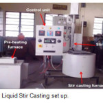
The challenging factor in the preparation of composite is to maintain the proper dispersion of reinforcement to achieve a defect free microstructure or the matrix and fiber interface. The liquid state stir casting is preferred rather than any other process because of its uniform distribution of fibers in the matrix during the mixture. If the alternative process such as powder metallurgy is carried out, the fibers break or crack during the process. The AA7075 has a melting temperature of 477-6350C,many non-conventional process has been carried out using this metal such as rheo-casting, stir casting, compo casting, etc. for every cases the different microstructures were found in different cases. In our study the AA7075 and the coated carbon fibers are mixed using stir casting method. This involves high melting temperature and constant stirring. The carbon fiber used at the different weight percentage of 1, 2 and 3% with the total weight including the Al is 3 Kg. The long Aluminium ingots are cut into the required size and placed in the crucible which has a capacity of 5 Kg. The crucible is then placed in the stir casting machine and constantly heated till the Al melts i.e. up to 7000C. The coated carbon fibers and the moulds where the molten metal to be poured is placed in the muffle furnace and heated for 5000 C. The carbon fibers are maintained the same temperature till it is transferred to the Al melt. When the Al melts at 7000C the Magnesium metal powder with weight percentage of 0.3% of total weight (10 grams) is poured into the melt. This reduces the surface tension of the Al and encourages the uniform mixture of the carbon fiber in the Al melt. The stirrer is placed one third to the height of the crucible which will be partly immersed in the Al melt. The stirrer is rotated at speed of 320 RPM which forms the vortex in the melt. The complete stir casting setup is as shown in the Fig. 3. The heated weighed carbon fibers are poured into the crucible for mixture with the Al melt. When the carbon fibers are poured simultaneously the stirrer has to be stirred at the constant speed, this helps the fiber to be immersed in the Al melt and allow the fibers to spread wide over inside the crucible. Stirring is continued till the matrix and the reinforcement interacts between each other and promoted wettability. Then the melt with the crucible is removed from the heater and poured into the heated mould. After the melt is poured, it is then left out for cooling for around 3 hours and the mould specimen is separated out for any testing process.
Figure 3: Liquid Stir Casting set up.
Testing of Specimens
All tests were directed as per ASTM standards. Tensile tests were organized at room temperature utilizing a universal testing machine (UTM) as per ASTM Standard E 8-82. The specimens of width 8.0 mm and gauge length 75 mm were machined from the cast composites with the gauge length of the examples parallel to the longitudinal axis of the castings. For every composite, four test samples were tried and the general estimations of the UTS (as far as rate prolongation) were measured. Each result is a normal of four readings.
Results and Discussions
Morphology of Electro Less Nickel Coating
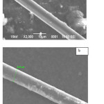
The SEM image which is shown in the Fig. 4(a) shows the uncoated carbon fibers which has the mean diameter of 7.16µm.The nickel coating that is deposited on the carbon fibers under the coating procedure. The Fig. 4(b) shows the coating thickness of 0.64µm over the carbon fiber as seen under SEM model JEOL JSM 6360 with a magnification capacity of X500, X1000, X2000 and accelerating voltage of 15 kV with a working distance of 10 mm. The uniform coating is maintained over the carbon fibers by employing uniform wettability over the matrix in order to give good adhesion and protection. The microscopic image reveals that the thickness and the morphology of the coating is maintained uniform under the time variant of sensitization, metallization and activation at 5, 15 and 3 minutes respectively.
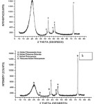
The X-ray Diffraction graph describes the mixture of solution that undergone for the preparation of a nickel coating on the carbon fiber. This can be determined with the graph plotted intensity vs. the angle 2β and the software PCPDFWIN to determine the mixture solution which is allotted for the peaks. The X-ray diffraction has an emitter and collector to study the diffraction occurred when the light beam comes in contact with the object. For the uncoated and nickel coated carbon fibers as shown in the Figs. 5(a) and 5(b), the angle 2β shows the angle of refraction of light to the reference beam. Accordingly for the certain angle of refraction and the certain input in the software the presence of solution at the particular angle can be determined which is the solution that accommodate for achieving the nickel coating on carbon fiber. The uncoated carbon fiber shows a Carbon content of 92% present in the processed carbon fiber.
Figure 4: SEM micrograph a) uncoated carbon fiber diameter; b) Coated carbon fiber diameter.
Figure 5: a) X-ray diffraction of uncoated carbon fiber; b) X-ray diffraction of nickel coated carbon fiber.
Tensile Properties
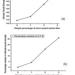
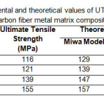
The plot for ultimate tensile strength (UTS) with a variety of short carbon covered fibers in metal matrix composite is appeared in the Fig. 6(a). It is observed that there is an increase in the ultimate tensile strength (UTS) over the variety of scattered fibers. This phenomenon is elaborated by studying the percentage variation in the UTS value from as cast Aluminum 7075 combination for various weight percentages of reinforced carbon fibers as appeared in Fig. 6(b). It has been noted that for variation in the fibers from 0 to 1% there was increment in the UTS estimation of 4.35%. Further increment up to 3% has demonstrated the UTS esteem addition to 26.11%. The presence of carbon filaments has ascribed the expansion in the UTS esteem which credits to the increment in the quality of general metal lattice composite. Better the grain estimate size better is the hardness and strength of composites inciting bringing down of wear rates. The development in UTS is attributed to the proximity of hard carbon short fiber, which gives quality to the grid combination, thereby enhancing its rigidity. Vogelsang et al.20 assumes that the adjustment in UTS may be a direct result of the strengthening of the matrix. The reasons dispensed are diminishment in the alloy grain size and start of a high dislocation density in the matrix, which is an outcome of the qualification in warm development between the metal grid and the short carbon fiber support. In the present examination two models in particular, Miwa model and modified model have been utilized for correlation of hypothetical quality with experimental results. The theoretical values developed by two models are introduced in the Table 2. The experimental results are in great concurrence with the hypothetical models in within an error of less than 15%.
Figure 6: Variation of a) UTS; b) Percentage vari ation of UTS, with respect to Weight percentage of the short carbon fiber.
Fracture Surface
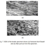
The general components of the microstructure, e.g. fiber orientation, and volume fraction were concentrated on utilizing a microscope and fractured surfaces were studied utilizing an examining electron magnifying lens. Average fractured surfaces of short carbon fiber composites, acquired from tensile tests, are demonstrated Fig. 7(a). As per Sood et al.21 the experiments conducted likewise propose that short fibers once in a while crack. Just not very many fibers can be seen as cracked and there is likewise a confirmation of ductile failure in the matrix. The disappointment is couple of strands split longitudinally and transversally as appeared in the Fig. 7(b). The failure of fibers in the composite might be credited to the expansion in weight on the stress of the specimen Sanders et al.22
Figure 7: SEM of the tensile specimen shows (a) fractured short Basalt fibers and (b) fiber puIl out from the specimen.
Table 2: Comparison of experimental and theoretical values of UTS of as cast Al 7075/ short coated carbon fiber metal matrix composite.
Conclusions
The tensile properties of the Al7075 alloy short coated carbon fiber composites are altered by the addition of the different weight percentage of carbon fiber.
- The electro less coating of the carbon fibers were uniform with the coating thickness of 0.6 – 1µm with Activation, sensitization and metallization stages at different time intervals.
- The stir casting technique with the addition of Magnesium metal powder improved the mixture ability of the AA7075 metal matrix with the coated carbon fiber.
- The ultimate tensile strength is found to be increasing by 13.80, 29.45, and 41.25% with increase of weight percentage of carbon fiber value which attributes to the increase in the strength of overall metal matrix composite The increase in UTS is due to the hard carbon short fiber, which confers quality to the lattice combination giving improved tensile strength
- There has been a considerably good agreement between the theoretical model values and the experimental results obtained for Ultimate tensile strength value of short carbon coated as cast Al 7075 alloy composite.
- The fracture was ductile showing fiber debonding, and fiber cracking.
References
- Ward P. J., Atkinson H. V., Anderson P. R. G., Elias L. G., Garcia B., Kahlen L and Rodriguez-Ibabe J. M. Semi- Solid Processing of Novel MMCs Based on Hypereutectic Aluminium-Basal Short Fiber Alloys. Acta Mater. 1996;44:1717-1727.
CrossRef
- Ward-Close C. M., Chandrasekaran L., Robertson J. G., Godfrey S. P and Murgatroyde D. P. Advances in the Fabrication of Titanium Metal Matrix Composite. Mater. Sci. Eng. (A). 1999;263:314-318..
CrossRef
- Gupta N., Satyanarayana K. G. Symposium Review: Solidification Processing of MMCs. J. Mater. Sci. 2006;5891-93.
- Miracle D. M etal. Matrix Composites-From Science to Technological significance. Compos. Sci. Technol. 2005;65:2526-2540.
CrossRef
- Evans A., Marchi C and Mortensen A. Metal Matrix Composites in Industry: An Introduction and a Survey. Kluwer Academic Publisher, Dordrecht. 2003.
CrossRef
- Ibrahim I. A., Mohamed F. A and Lavernia E. J. Particulate Reinforced Metal Matrix Composites. J. Mater. Sci. 1991;26:1137-1156.
CrossRef
- Chou T. W., Kelly A and Okurat A. Composites de Matrices en Métal Renforcés aux Fibres. Compos. 1985;16:183-184.
CrossRef
- Kelly A., Fishman S and Dhingra A. Proceeding International Symposium on Advances in Cast Reinforced Metal Composite, Chicago. 1988.
- Wessel J. K. The Handbook of Advanced Materials, 2ndedn,(John Wiley & Sons Inc., New Jersey, USA). 2004.
- Everett R. K., Arsenault R. J. Metal Matrix Composites: Mechanisms and Properties. Academic Press.San Diego. 1991.
- Kocjok MJ, Kahtri SC, Allison JE, Jones JW. Fundamentals of metal matrix composites. Butterworth- Heinemann. Boston.
- Ramnat BV, Elanchezhian C., Annamalai RM, Aravind S, Atreya TA, Vignesh V, Subramanian C. Aluminium metal matrix composites- A review. Rev. Adv. Mater. Sci. 2014;38:55-60.
- Raviteja T, Radhika N, Raghu R. Fabrication and mechanical properties of stir cast Al-Si12Cu/B4C composites. Int. J.Res.Eng. Technol. 2014;3:343-346.
CrossRef
- Himanshu K, Mer KKS, Kumar S.A Review on Mechanical and Tribological Behaviors of Stir Cast Aluminium Matrix Composites, Proc. Mater. Sci. 2014;6:1951–1960.
- Zhongcai S, Zhang Y, Xia NZJ.Preparation and research of electro less copper on carbon fibers. Mater. Manufac. Proc. 2016;3112-17.
- Bhav BS, Balasubramanian M. Processing and properties of copper coated carbon fiber reinforced Aluminium alloy composites. J.Mater. Proc. Technol. 2008;209:2104-2110.
CrossRef
- Hajjari E, Divenari M, Mirhabibi AR. The effect of applied pressure on fracture surface and tensile properties of nickel coated continuous carbon fiber reinforces Al composites fabricated by squeeze casting.Mater.Des. 2010;312381-2386.
- Silvain JF, Heintz JM, Lahaye M. Interface analysis in Al and Al alloys/Ni/Carbon composites. J. Mater. Sci. 2000;35961-965.
- Zhang H, Zhang Z, Friedrich K. Effect of fiber length on the wear resistance of short carbon fiber reinforced epoxy composites. Compos. Sci. Technol. 2007;67222–230.
CrossRef
- Vogelsang M, Arsenault RJ, FisherRM. An in Situ HVEM Study of Dislocation Generation at Al/SiC Interfaces. Met. Trans. A. 1986;17:379-389.
CrossRef
- Sood J, Tiwari, AN, TeredesaiA. TiC-Reinforced Al Matrix Composites. Proceedings of 2nd Inter- national Conference on Aluminium INCAL-91, Aluminium Association, Bangalore, India. 1991.
- Sanders BR, Weintraub TL.ASM Handbook. Mechanical Testing. American Society of Metals. 1995.

This work is licensed under a Creative Commons Attribution 4.0 International License.