Krishnaprakash Arunachalam1 and Monikandon Sukumaran2*
1Department of Civil Engineering, University College of Engineering Nagercoil, Kanniyakumari, 629004, Tamil Nadu, India
2Department of Basic Engineering, College of Fisheries Engineering, Tamil Nadu Fisheries University, Nagapattinam 611 001, Tamil Nadu, India
Corresponding author Email: monicivil.engineer@gmail.com
DOI : http://dx.doi.org/10.13005/msri/140108
Article Publishing History
Article Received on : 1 Mar 2017
Article Accepted on : 22 Mar 2017
Article Published : 08 May 2017
Plagiarism Check: Yes
Article Metrics
ABSTRACT:
This paper describes the analysis of scaffold frame intersection joint crack. Independent scaffolding type is selected and analyzed for the cracks and deformations. The modelling of the structure is done with the Solid works software and the rendered model was imported to ADINA structures software. All the dimensions for the scaffold design were followed as specified in the standard codes BS4945. Live loads of 2kN/sq.m were taken. The post processing is executed and the results were generated. The results show that maximum bending moment 11.94N-m is at intersection joints particularly at joints. The minimum bending moment -13.44N–m has occurred below the junction the effective stress calculated around the junction of the scaffold is 3.493N/mm
2 and the deformation of the scaffolding frame is at intersection joints and the cracks are formed. Visualizing the crack by using ADINA may be the best way to estimate the deformation modes and crack. This will definitely be useful for the remedial measures to prevent cracks in a scaffold structure.
KEYWORDS:
ADINA Structures; Crack visualizing; Crack failure analysis; Deformation of Scaffold; Independent scaffold type
Copy the following to cite this article:
Arunachalam K, Sukumaran M. Crack Failure Analysis of Scaffolding Frame Intersection using ADINA. Mat.Sci.Res.India;14(1)
|
Introduction
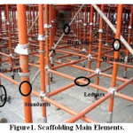
Scaffolds are temporary structures commonly used in construction to support various types of loads.12 The temporary structure needs to be structurally safe yet also capable of rapid erection, disassembly and reuse. Scaffolding is used on new building projects, and for existing structure including maintenance, repair and painting work. In Building construction some form of temporary support is required to provide a safe and convenient working area above ground level.8 The main elements of scaffolding are standards, ledgers, transoms, base plate, base jack and diagonal bracings.8 Figure 1 represents the main elements of the scaffolding structure. The scaffolding failure occurs due to crack/collapse due to excess load, poor design of the scaffolding structure.10 Generally steel tubular scaffoldings are used due the high strength, durability as well they can be reused. The diameter of the tubular steel used as ledgers and standards vary from 42mm to 48mm with the approximate thickness of 3mm.12,13,14 Scaffolding for the single storey double bay scaffolds with boundary conditions, joints are assumed as rigid were reported.1 The objective of this paper is to describe the analysis of scaffold frame intersection joint crack for independent scaffolding using ADINA structures software.
Experimental
Modelling of scaffold frame
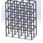
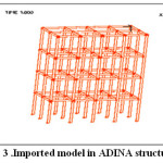
The scaffold model is created for G+1 residential building using Solid works software. Scaffold frame sections are designed for the 6 m x8 m side wall. Selected model was independent scaffolding frame system and Table 1 describes the dimension of the scaffolding frame. After completing the scaffolding model the section are saved as the parasolid (X_t) model type. Figure 2 represents the independent scaffold model for G+1 residential building using solid works software, which imported to the ADINA structures software as shown in Figure 3.
Design Procedure
The following design principles are used in creating the model and analyzing the scaffold frame intersection
- Defining Model Geometry
- Specifying Boundary conditions
- Applying loads and material properties
- Meshing
- Post-processing
Figure 1: Scaffolding Main Elements
Figure 2: Scaffold Design using Solid works
Figure 3: Imported model in ADINA structures
Defining model geometry
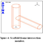
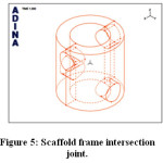
The model geometry already done with the help of solid works is imported to ADINA structures. The Import model is saved in the parasolid format and the analysis are done for the intersection and joints. The intersection member and the intersection joints of the scaffold frame are shown in figures 4 and 5 respectively.
Figure 4: Scaffold frame intersection member
Figure 5: Scaffold frame intersection joint
Specifying Boundary conditions
The boundary conditions are given through the fixity icon. It is used to fix some or all degrees of freedom on certain parts of model to geometric entities or sets of nodes, element faces/edges.
Applying Loads and Material Properties
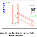
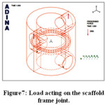
Load conditions are applied using load icon. Live loads of 2kN/sq.m were taken. Load acting on the scaffold frame intersection members are generally considered as distributed load and for intersection joints it is considered as point load. Figure 6 shows the load acting on the ledgers (ie) the horizontal member of the scaffold frame. For scaffold frame joints load are considered as the same value given on the scaffold frame member. After applying the load we can visualize the cracks formed between the junctions of the scaffolding frame. Figure7 evidently shows the load acting on the joints of the intersection frame and also the crack formed. Young’s modulus 2.07E11 and the Poisson’s ratio 0.29 are taken as common material properties for both the intersection frames and intersection joints frame sections.
Figure 6: Load acting on the scaffold frame member
Figure 7: Load acting on the scaffold frame joint
Meshing
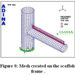
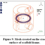
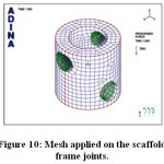
Meshing is performed to generate finite elements on geometry in the model. Figure 8 represents the mesh created on the surface of scaffold intersection member. For cracks which are formed inside the scaffold frame junction also meshing group elements are created. Figure 9 represents the mesh created on the crack surface. Figure 10 shows the meshing group elements created for the scaffold frame joints
Figure 8: Mesh created on the scaffold frame
Figure 9: Mesh created on the crack surface of scaffold frame
Results and Discussion
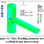
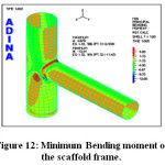
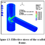
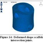
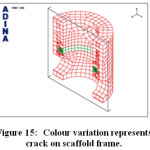
Post-processing method helps in getting the results. The output model (.por) file is open with the help of post-processing AUI database. The concentration of bending moment at intersection particularly joints are getting higher value. From figure 11 and graph red colour indicates higher bending moment. The graphics window show the maximum bending moment as 11.94 N-m. From figure 12 and the graph, blue colour represents minimum bending moment has occurred below the junction. The graphics window shows the minimum bending moment is -13.44 N-m. The graphics window and figure 13 shows the maximum effective stress as 3.493 N/mm2 which is calculated around the junction of the scaffold frame. Figure 14 shows that deformations take place due to applied load and the round shape scaffold gets deformed. After deformation it is similar to oval shape and deformation of the scaffold frame is at intersection joints. Figure 15 shows the difference between the crack and scaffold frame structure joints. Cross sectional views can clearly make understand the crack formation inside the structure. The colour variation also helps to understand the purpose. This shows the exact crack design can be visualized in the ADINA structures.
Figure 10: Mesh applied on the scaffold frame joints
Figure 11: Max Bending moment on the scaffold frame intersection
Figure 12: Minimum Bending moment of the scaffold frame
Figure 13: Effective stress of the scaffold frame
Figure 14: Deformed shape scaffold intersection joints
Figure 15: Colour variation represents crack on scaffold frame
Table 1: Design Parameters and specifications used
| Parameters |
Specifications |
| Pipe Diameter |
48 mm |
| Pipe Thickness |
4 mm |
| Lift Height |
2 m |
| Scaffold Width |
3 m |
Conclusion
This paper using ADINA structures shows that the crack could possibly occur in the joints of scaffolding. Using ADINA structures estimation of deformation modes can be done with accuracy. All the stresses, strains and other calculations can also be computed and analyzed. Visualizing cracks will definitely be useful for the remedial measures to prevent cracks in a scaffold structure.
Acknowledgement
Monikandon Sukumaran thanks College of Fisheries Engineering, Tamil Nadu Fisheries University Nagapattinam for motivation towards research.
References
- Chu A. Y. T., Chan S. L., Chung K. F. Stability of modular steel scaffolding systems – theory and verification. Proceedings of International Conference, Advances in Building Technology, Hong Kong. 2002;621-628.
- Godley M. H. R., Beale R. G. Analysis of large proprietary access scaffold structures. Proceedings of the Institution of Civil Engineers: Structures and Buildings.UK. 2001;146:31-39.
CrossRef
- Godley M. N. R and Beale R. G. Sway Stiffness of Scaffold Structures. The Structural Engineer. 1997;75(1).
- Gylltoft K., Mroz K. Load carrying capacity of scaffolds. Structural Engineering International. 1995;1:37-42.
CrossRef
- Enright J., Harriss R and Gregory J. Hancock Structural Stability of Braced Scaffolding and Formwork with Spigot Joints. International Specialty Conference on Cold-Formed Steel Structures. 2000;2.
- Jui-Ling P., Chi-Ling P., Kuan-Hung C and Siu-Lai C. Structural Analysis of Scaffolding with the Plank and Anchor Rod During Construction. International Specialty Conference on Cold-Formed Steel Structures. 2008;14:3.
- Lightfoot E and Oliveto G. The Collapse Strength of Tubular Steel Scaffold Assemblies, Proceedings. Institution of Civil Engineers. 1997;2(63);311-329.
- Varghese V. M. A Concept for Development, Safe Erection and Use of Scaffolding for High Rise Buildings ,International Journal of Innovative Technology and Exploring Engineering. 2012;1(2):224-226.
- Diering R. M. Ergonomic evaluation of scaffolding task interventions for power plant maintenance, http://www.lib.ncsu.edu/resolver/1840.16/1034, accessed Date 18.04. 2016.
CrossRef
- Peng J. L., Chan S. L., Wu C. L. Effects of geometrical shape and incremental loads on scaffold systems. Journal of Constructional Steel Research. 2007;63(4):448-459.
CrossRef
- Lacalle R., Cicero S., Ferreno D., Alvarez J. A. Failure analysis of a bolt in a scaffolding system. Engineering Failure Analysis. 15(3)2008;237–246.
CrossRef
- Chandrangsu T., Rasmussen K. J. R. Review of past research on scaffold system, Research Report No R. 905. 2009.
- Chandrangsu T., Rasmussen J. R K. Structural Modelling of Support Scaffold Systems, Research Report No R 896. 2009.
- Chandrangsu T., Rasmussen J. R. K. Scaffold cuplock joint test, Research Report No R893, December 2008.
- Valerii V. Comparison of scaffolding system in Finland and in Russia, Saimaa University of Applied Sciences Technology, Lappeenranta, Bachelor Thesis 2011.
- Yu W. K., Chung K. F., Chan S. L. Structural instability of multi-storey door-type modular steel scaffolds. Engineering Structures. 2004;26(7):867-881.
CrossRef
J

This work is licensed under a Creative Commons Attribution 4.0 International License.