Mechanical Behavior and Phase Analysis of Friction-Stir Welded AA-6061 Alloy
 , Diego Sánchez-García1 and Víctor Manuel Castaño-Meneses2
 1Department of Engineering, National Autonomous University of Mexico, Mexico State, Mexico.
2Department of Nanotechnology, National Autonomous University of Mexico, Querétaro, Mexico.
Corresponding Author E-mail:jaimeht@unam.mx
DOI : http://dx.doi.org/10.13005/msri/220207
Download this article as:
![]()
Flat plates of AA 6061 alloy were welded by using friction-stir welding technique. The plates were placed in direct contact to the bench of the tool holder machine and mechanically fixed, with the bench functioning as a cooling substrate. For the friction-stir welding tool, the optimal values of spindle speed and feed rate were 1045 rpm and 18.6 mm/min, respectively. The welded plates were mechanically characterized in terms of Vickers microhardness (HV), ultimate tension strength (UTS), yield point (YP) and elongation to failure (EF). The weld bead showed a decrease in hardness of 33 % approximately. Tension test results of the welded plates showed UTS, YP and EF were reduced to 66, 60 and 33 % in relation to those of the base metal. X-ray diffraction analysis revealed the presence of q (Al2Cu), Q' (Al3Cu2Mg9Si7), β² (Mg5Si6), β¢ (Mg9Si5), aAl and Al phases inside the weld bead, while the base metal showed to contain β² and β¢ precipitates inside the Al-rich matrix. Heat treatment of solid solution and ageing at 433 K by 18 hours increased the weld bead hardness to 110 HV in the welded plates.
KEYWORDS:Deformation and fracture; Friction-stir welding; Metastable phases; Phase transformation; Second phase; Weld bead
Introduction
The manufacture of Al-based Alloys structures has as main technical challenge the welding of plates and profiles. When conventional welding processes are utilized (electric arc) small zones are melted then cooled; consequently, the melted zone will be conformed by dendrites containing metastable phases, defects, and strange material (mainly oxides). To avoid the introduction of oxides and other materials with different chemical composition, the friction-stir welding technique has been considered as an alternative, it being important to point out that each type of alloy requires a special welding tool and the determination of parameters (spindle speed, feed rate). This technique was invented in The Welding Institute in Cambridge, England (in 1991) and patented in United Kingdom1-4 and in United States of America for the welding of aluminum alloys.5
In the friction-stir welding technique is important to mention that entrance of heat, generated by the friction among the plates and the rotational tool, causes atomic excitation inside both plates around the welding line; such excitation increases the d-spacing and diminishes the atomic bond intensity, allowing material to slide from one side of the weld line to the other. Based on theory, the rotation of the tool in contact with the plates, it would cause the slip of the atomic planes (slip systems) and the slip through the grain boundaries. Under this state of stir, material of a plate is transported toward the other one, creating a zone of instability named weld bead.
By utilizing the friction-stir welding technique in AA 6061-T6 alloy, Tao et al. found the presence of β¢ and b phases inside the weld bead and, depending on the feed rate, the u-phase or type-A phase is also present.6 Fathi et al. performed the friction-stir welding to this same alloy in an underwater condition, finding that the tensile strength and hardness can be improved while the elongation decreases.7 Complementary to the above, Andersen et al. determined that the needle-shaped b² is the most important hardening precipitate in Al-Mg-Si alloys.8
By using the friction-stir welding technique AA 6061 alloy plates were welded. In the experimental assembly a cold solid substrate in contact with aluminum couples was utilized. The main objective is to determine the effect on the mechanical behavior of the ensemble plate-weld bead-plate, as well as to analyze the phases that are present in the weld bead, everything caused by the described welding technique and the established cooling conditions.
Materials and Methods
Welding tools were machined in H13 tool steel and heat-treated. The welding tool that gave the best results has a concave shoulder (24 mm, diameter) prolonged by a conical pin (opening angle a = 7°). Regarding the conditions for friction-stir welding technique, the parameters were experimentally optimized; the optimum spindle speed was 1045 rpm, and the average feed rate was 18.6 mm/min.
Rectangular plates (26 x 10 cm, 0.6 cm thick) of AA 6061 commercial alloy were utilized (Table 1). Two work pieces were placed butt through the longest side and fixed on the bench of the milling machine (OIMSA FTX-8). The resulting couple was welded employing the friction-stir welding technique. From welded couples tension test samples with shape and size according to ASTM E8/E8M standard were machined, and a universal machine of tests (PTS FMCC-100) with a capacity of 100 kN was employed; a strain rate of 1 mm/min was established.
For the crystallographic analysis, an x-ray diffraction apparatus (Rigaku Ultima IV) was utilized. The wavelength of nickel filtered x-rays was 1.54 Å. Circular sections (20 mm, diameter) were extracted from the start plates and the weld bead for irradiation.
Table 1: Chemical composition of AA-6061 alloy (weight %).
| Element | Mg | Si | Cr | Mn | Fe | Cu | Al |
| AA-6061 | 1.2 | 0.49 | 0.16 | 0.03 | 0.38 | 0.28 | Balance |
Results
The image at the bottom of Figure 1 schematically describes the profile of the weld bead achieved with the technique described. As it can be seen, the straight line of the weld bead is collinear with the line of the plate; in practice, this line presented small irregularities caused by the rotating tool. Towards the bottom of the weld bead profile, the contour of such zone is delimited by a concave curve.
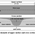 |
Figure 1: Schematic of upper surface and cross section of weld bead. |
The presence of second-phase particles within the weld bead and base material was observed by optical microscopy; these particles have varied shapes and sizes. The image in Figure 2 shows the presence of precipitates in welded joint and thermo-mechanically affected zones; in addition, in welded area, it can be viewed that the size of the precipitates is more homogeneous and with more regular particles distribution.
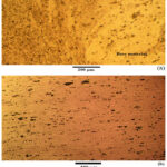 |
Figure 2: Optical micrographs of weld bead cross-section showing precipitates distribution: (a) base material (light yellow) and weld bead (dark yellow); (b) cross-section center. |
The Vickers microhardness on the weld bead surface and in its respective cross section are graphically shown in Figure 3. The hardness profiles shown give the half values obtained in samples only welded (black graph) and samples with heat treatment (color graph); the hardness measures were executed in perpendicular direction to joint line remarking that the weld bead width in the surface was 25 mm.
As can be observed, the hardness inside the weld bead is reduced significantly (63 HV) with respect to the base material (92-95 HV); this reduction in hardness is caused by the generated heat (causing phase transformation) and the severe granular deformation that are produced by the mechanical stir. Hardness measures conducted at half depth (2.6 mm) of the cross section of concave shape (5.3 mm maximal depth) show a similar behavior.
To improve the mechanical resistance of welded plates, the plate couples were subjected to a solid solution heat treatment then aged by periods of 8, 12, 18 and 20 hours prior to tension test. From hardness profiles graphs, for an ageing time of 18 hours a notable increase in this property can be achieved.
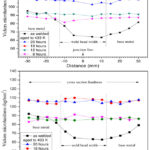 |
Figure 3: Hardness profiles of weld bead and contiguous zones. |
After applying the described welding technique to AA-6061 alloy plates, the weld bead presented a softer character than the base material. Regarding mechanical behavior in tension, the measures of deformation and fracture showed a decrease in the mechanical resistance of welded couples. Table 2 shows average values of ultimate tensile strength, yield point and elongation to failure, that were obtained from a typical deformation diagram. For the ultimate tensile strength, a reduction of 66 % was obtained, while for the yield point and elongation to failure the reductions were of 60 and 33 %, respectively.
Table 2: Mechanical properties under tension obtained from a typical deformation diagram. Average values, S.D. Standard Deviation.
| Ultimate tensile strength(MPa) | Yield point(MPa) | Elongation to failure(%) | |
| Base material | 334.4S.D.: 2.47 | 274.2S.D.: 6.35 | 12.3S.D.: 1.06 |
| Welded couples | 111.15S.D.: 4.64 | 108.9S.D.: 6.86 | 8.2S.D.: 0.51 |
Andersen et al. mention that the mechanical resistance in the AA6xxx system is attributable to the presence of the needle-shaped precipitate βʹʹ phase.8 Therefore, the tensile strength reduction in welded couples can be principally due to a transformation of such phase as consequence of heating caused by welding process.
X-ray diffraction spectra obtained from the plates and weld bead are shown in Figure 4. Base metal spectrum shows the phases in the plates before welding. The majority phase is clearly defined through the reflections at 38.1°, 44.4°, 64.8° and 77.9° (2θ); nevertheless, regarding the intensity of the reflection at 38.1°, this reflection presents the lowest intensity with respect to the other reflections corresponding to this phase. The anterior can be explained as the result of the previous mechanical work carried out on the plate; being that the plastic deformation to reach a plate thickness of 6 mm, it reduced the number of (111) planes oriented in Bragg’s conditions (preferential orientation) and the total disappearance of the reflection of the (222) plane. Second phases as β² and β¢ can also be observed in the base metal spectrum. Regarding the structures of second phases, the analysis of the diffraction patterns was made based on reported data. Zandbergen et al. report β¢¢ phase has a monoclinic unit cell with dimensions a = 15.16 Ǻ, b = 4.05 Å, c = 6.74 Å and β = 105.3°.9 Vissers et al. report that β¢ phase has a hexagonal unit cell with a = 7.15 Å and c = 12.15 Å.10
In the case of the weld bead, x-ray diffraction was conducted on extracted sections from the weld bead (weld bead spectrum in Figure 4a). The reflections corresponding to the aluminum-rich phase are markedly intense except for the peak at 82.3° (2θ). This fact allows us to suppose that the entrance of heat and the displacement of material increased the number of (111) and (222) planes oriented favorably for diffraction. In addition, the upper spectrum shows the presence of two new phases, the Qʹ (Al3Cu2Mg9Si7) metastable phase and the θ (Al2Cu) stable phase. To support this last, the reflections at 34.4° and 29.2° (2θ) are evidencing the presence of Qʹ and θ phases in the weld bead, since each peak corresponds to independent reflections of these phases, respectively. For the analysis of these phases, what was reported in the literature was used. Arnberg and Aurivillius report the crystal structure of Qʹ phase; according to their research, Qʹ phase has a hexagonal unit cell with a = 10.39 and c = 4.02 Ǻ.11 Meetsma et al. they reported the crystal structure of θ (Al2Cu) phase, according to their research this phase has a tetragonal unit cell with a = 6.067 and c = 4.877 Ǻ.12 In the literature is mentioned that others transitional phases as the “u-phase” (Al2MgSi2) or the “type-A” (Al4MgSi5) phase are present in the weld bead (nugget zone),6 but in this study these phases were not observed probably because of that the experimental conditions (1045 rpm, 18.6 mm/min) were different, which modified the thermodynamics of the precipitation.
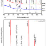 |
Figure 4: X-ray diffraction spectra of AA 6061 alloy welded plates. (a) Weld bead and base metal; (b) Image showing double reflections of aluminum-rich phase of (222) diffraction plane. |
Discussion
By considering the function of the precipitates in the reinforcement or softening of the alloy, the following hypothesis can be established. The nucleation and growth of θ and Q’ precipitates in the weld bead was the result of the atomic diffusion caused by a fast heating (~ 573 K) followed by a slow cooling after having passed the tool throughout the juncture line. Complementary to the atomic diffusion, it is possible that the assisted glide gave place to the coalescence of different second phases then react. Literature reports indicate that the metastable Q’ phase appears after a prolonged aging and, the presence of this phase is associated with a reduction in the alloy strength.13,14 Miao and Laughlin carried out calorimetric studies of 6111 alloy with pre-aging treatments, they observed that the precipitation of βʹ and/or Qʹ caused a reduction on hardness.15 In addition, the growth of the volume fraction of the Q’ phase will reduce the volume fractions of the hardening phases (β”, θ), which explains the mechanical behavior of the weld bead. In addition, it is important to mention that the nucleation and growth of the Q’ and θ phases is conducted to expense of the solute in the αAl solution, which results in a local transformation of αAl into Al. In detail, the reflections at 64.8°, 77.9° and 82.3° (2q) in the weld bead spectrum (Figure 4b) shows double peaks; this fact can be clearly viewed in reflection at 82.3° (2q) in Figure 4b, where the band is formed by two peaks of different intensity. This last implies that in the welded area, the aluminum-rich phase will contain zones with different cell parameters (aAl + Al), the above can be verified using the EDX technique in different areas of the weld bead. Finally, to complement the study, in relation to shape and distribution of precipitates, the use of scanning electron microscopy would be necessary. Currently, work in this direction is being carried out.
Conclusions
AA 6061 alloy plates were welded by friction-stir and their mechanical behavior in tension was analyzed. Considering the initial properties of unwelded plates, the values of UTS, YP and EF for the “plate-weld bead-plate” assemblies were reduced to 66, 60 and 33 % on average, respectively. Hardness measures conducted from base metal up to weld bead on the “plate-weld bead-plate” assemblies showed a hardness drop of 33 %. The bench and machine body functioned as a cooling substratum; this condition combined with the welding process caused the low mechanical resistance observed on “plate-weld bead-plate” assemblies. The X-ray analysis showed: the β², β¢ and αAl phases are present in the initial flat plates; whereas, the q , Q¢, β², β¢, Al and αAl phases are present inside the weld bead. The heat treatment of solid solution and ageing by 18 hours increased the hardness in the weld bead from 63 up to 110 HV. Under the mentioned conditions, the welding process by friction caused the observed phase transformations and promoted the formation of an unstable structure along the welding line. The poor mechanical qualities that caused this welding process were improved by adding the heat treatment described in this work.
Acknowledgements
This research was supported by the Institution Research Projects Program PIAPI2025. The authors express their gratitude to technician Noé Cortés Guerrero (Machine and tool workshop, FESC-UNAM), Dra. Beatriz Millán Malo (X-ray diffraction laboratory, CFATA-UNAM).
Funding Source
The author(s) received no financial support for the research, authorship, and/or publication of this article.”
Conflict of Interest
The authors do not have any conflict of interest.
Data Availability Statement
This statement does not apply to this article
Ethics Statement
This research did not involve human participants, animal subjects, or any material that requires ethical approval
Informed Consent Statement
This study did not involve human participants, and therefore, informed consent was not required
Authors’ Contribution
- Diego Sanchez-García: Data Collecttion, Analysis.
- Víctor M. Castaño-Meneses: Conceptualization, Review & Editing.
- Jaime Hinojosa-Torres: Data Collection, Methodology, Analysis, Writing, and final approval of the manuscript.
References
- Thomas W. M., Nicholas E. D., Needham J. C., Murch M. G., Temple-Smith P. & Dawes C. J., International Patent Application No. PCT/GB92/02203 and GB Patent Application No. 9125978.8, (1991).
- Thomas W. M., Nicholas E. D., Needham J. C., Murch M. G., Temple-Smith P. and Dawes C. J., PCT World Patent Application WO 93/10935. Filed: Nov. 27, 1992 (U.K. 9125978.8, Dec. 6, 1991). Publ: June 10, (1993).
- Thomas W. M., Nicholas E. D., Needham J. C. Temple-Smith P., Kallee WKW S. and Dawes C. J., U.K. Patent Application 2,306,366A, Filed: Oct. 17, 1996. Publ: May 7, (1997).
- Thomas W. M., Murch M. G., Nicholas E. D., Temple-Smith P., Needham J. C and Dawes C. J., European Patent Application 653,265A2. Filed: Nov. 27, 1992 (U.K. 9125978, Dec. 6, 1991). Publ: May 17, (1995).
- Midling O. T., Morley E. J., Sandvik A., Application No. PCT/NO95/00005 United States Patent Application No. 718590. (1995).
- Tao W., Yong Z., Matsuda K. “Precipitation in the Nugget Zone of AA6061-T6 by Friction Stir Welding”. Chiang Mai Journal Science. 2016; 43: 409-419.
- Fathi J., Ebrahimzadeh P., Farasati R., Teimouri R. “Friction stir welding of aluminum 6061-T6 in presence of watercooling: Analyzing mechanical properties and residual stress distribution”. International Journal of Lightweight Materials and Manufacture. 2019; 2: 107-115.
CrossRef - Andersen S. J., Marioara C. D., Friis J., Wenner S. & Holmestad R. “Precipitates in aluminium alloys”. Advances in physics: X. 2018; 3: 790-814.
CrossRef - Zandbergen H. W., Andersen S. J. and Jansen J. “Structure Determination of Mg5Si6 Particles in Al by Dynamic Electron Diffraction Studies”. Science. 1997; 277: 1221-1225.
CrossRef - Vissers R., M. Van-Huis A., Jansen J., Zandbergen H. W., Marioara C. D., Andersen S. J. “The crystal structure of the b¢ phase in Al-Mg-Si alloys”. Acta Materialia. 2007; 55: 3815-3823.
CrossRef - ARNBERG L. and AURIVILLIUS B. “The crystal Structure of AlxCu2Mg12-xSi7,(h-AlCuMgSi),” Acta Chemica Scandinavica A. 1980; 34: 1-5.
CrossRef - MEETSMA A., DE BOER J. L. and VAN SMAALEN S. “Refinement of the Crystal Structure of Tetragonal Al2Cu”. Journal of Solid State Chemistry. 1989; 83: 370-372.
CrossRef - MATSUDA K., SAKAGUCHI Y., UETANI Y., SATO T., KAMIOA., IKENO S. “Precipitation sequency of various kinds of metastable phases in Al-1.0mass%Mg2Si-0.4mass%Si alloy”. Journal of Materials Science. 2000; 35: 179-189.
CrossRef - Chakrabarti D. J. Yingguo Peng and David E. Laughlin. “Precipitation In Al-Mg-Si Alloys with Cu Additions and the Role of the Q’ and Related Phases”. AUTOMOTIVE ALLOYS, 1998 TMS annual Meeting (USA), San Antonio, Texas, February 14-19, 1998.
- MIAO W. F., LAUGHLIN D. E. A differential scanning calorimetry study of aluminum alloy 6111 with different pre-aging treatments. JOURNAL OF MATERIALS SCIENCE LETTERS. 2000; 19: 201-203.
CrossRef
Accepted on: 18 Sep 2025
Second Review by: Dr. Anand Patel
Final Approval by: Dr. Y S Reddy


![]()
![]()
![]()
![]()