Impact of PEDOT: PSS Electrode Work Function on DPPEZnP-TBO Based Active Layer in Tandem Organic Solar Cells

Department of Physics, B.R. Ambedkar Bihar University, Muzaffarpur, Bihar, India.
Corresponding Author E-mail: lahapinaki007@gmail.com
DOI : http://dx.doi.org/10.13005/msri/220303
Download this article as:
![]()
This study investigates the impact of electrode work function on the performance and efficiency of DPPEZnP-TBO-based tandem organic solar cell (OSC) devices, focusing on PEDOT: PSS as the electrode material. By adjusting the electrode's work function, we investigate its influence on the active layer's electrical properties and the device's key performance metrics, including open-circuit voltage (VOC), short-circuit current density (JSC), power conversion efficiency (PCE), and fill factor (FF). Changes in electrode work function are associated with significant differences in fill factor (FF), power conversion efficiency (PCE), open-circuit voltage (VOC), and short-circuit current density (JSC). The best performance is of tandem organic solar cell is achieved at a work function of 5.2 eV, with a JSC of 2.598 mA/cm², VOC of 1.16 V, PCE of 2.41%, and FF of 79.6%. Optimising the work function improves charge mobility and reduces recombination losses, enhancing overall performance. This research provides valuable insights into improving DPPEZnP-TBO solar cells for durable and scalable large-scale solar energy applications.
KEYWORDS:DPPEZnP-TBO; fill factor (FF); Organic tandem solar cells; Power conversion efficiency (PCE); Work function
Introduction
Population growth and the post-COVID industrial resurgence have led to a significant increase in energy demand. Researchers have suggested a variety of renewable energy sources to lessen reliance on fossil fuels, with solar energy emerging as the most favoured choice1-4. In recent decades, organic photovoltaic technology has garnered growing interest. Organic solar cells (OSCs) serve as a cost-efficient substitute for standard inorganic solar cells1,2. OSCs’ demand lies in their versatility, flexibility, lightweight design, and affordability5-8. To produce low-cost organic solar cells, it is highly desirable to eliminate metal electrodes and indium-tin-oxide (ITO), due to the high cost of ITO and its limited mechanical flexibility6, 9. Additionally, the deposition of metal electrodes requires high-vacuum environments, which are not conducive to cost-effective and large-scale production. Research on electrode work function is crucial as it governs charge extraction through proper energy level alignment between electrodes and active layers10. Proper alignment minimises interfacial barriers and enhances carrier collection in tandem cells. Organic solar cell devices are more stable and efficient when their work functions are optimised. Comparative summary of solar cell devices employing ITO/PEDOT: PSS-based electrodes, highlighting their fill factors and power conversion efficiencies in Table 111-15. Due to their superior transparency, high conductivity (above 1000 S/cm), and compatibility with solution-based processing methods like spin coating, spraying, and printing, conductive polymers, such as poly(3,4-ethylenedioxythiophene)–poly (styrene sulfonate) (PEDOT: PSS), have emerged as promising substitutes for ITO for bottom electrodes. PEDOT: PSS has also been utilised as a top electrode in organic solar cells with inverted structures 16–18. PEDOT: PSS is appropriate for hole collection in organic solar cells since it usually shows a working function of about 5.0 eV 19. Nevertheless, it is still difficult to obtain a low work function (LWF) PEDOT: PSS for electron collecting 20,21. In earlier methods, a ZnO layer was deposited on PEDOT: PSS to help with electron collection. According to recent research, organic compounds such as polyethylenimine (PEI) and polyethylenimine ethoxylated (PEIE) can successfully reduce the work function of different conductors, such as PEDOT: PSS. Researchers have created ITO- and metal-electrode-free organic solar cells utilising LWF-PEDOT: PSS, however, the device efficiencies have remained comparatively low, at about 3%22. The low fill factor (around 52%) resulting from PEDOT: PSS restricted conductivity is the main cause of this low efficiency value. According to recent research, sulphuric acid post-treatment can significantly raise PEDOT: PSS conductivity to over 2000 S/cm 19. This improvement has the potential to increase the efficiency of organic photovoltaic cells that use PEDOT: PSS as the top and bottom electrodes. Furthermore, although spin coating has historically been used to apply PEI and PEIE modifications to reduce the work function of PEDOT: PSS, this approach is not optimal for large-area fabrication23. Developing scalable methods to incorporate these materials will be crucial for advancing the performance and scalability of organic photovoltaic cells.
In this study, we simulate the performance of an organic solar cell device structure with ITO/PEDOT: PSS2/DPPEZnP-TBO2/ ZnO /PEDOT: PSS1/DPPEZnP-TBO1/Al layers at 300 K. The performance of the device is analysed using the Fluxim-SETFOS simulation software. We also study the open-circuit voltage (VOC), short-circuit current density (JSC), fill factor (FF), and power conversion efficiency (PCE) of OSCs to show how the electrode’s work function affects their performance.
Table 1. Comparison of PEDOT: PSS-based electrode solar cell devices with corresponding fill factor (FF) and power conversion efficiency (PCE).
| Sl. No. | Tandem Organic Solar Cells | Fill Factor
(FF) |
PCE (%) | Ref. |
| 1 | ITO/PEDOT: PSS/MDMO-PPV: PCBM/ ITO/PEDOT: PSS/MDMO-PPV: PCBM/Al | 56 | 3.1 | 9 |
| 2 | ITO/PEDOT: PSS/MEH-PPV: PCBM/Au/ ITO/PEDOT: PSS/ MEH-PPV: PCBM/Al | 45 | 2.4 | 10 |
| 3 | ITO/PEDOT: PSS/ MDMO-PPV: PCBM/ZnO/PEDOT/ P3HT: PCBM/Al | 40 | – | 11 |
| 4 | ITO/PEDOT: PSS/ PCPDTBT: PCBM/TiO2/PEDOT/ P3HT:PC70BM/TiO2/Al | 66 | 6.3 | 12 |
| 5 | ITO/PEDOT: PSS/ DPPEZnP-TBO: PC61BM/PFN/Al | 63.0±0.9 | 11.46 ± 0.28 (11.74) | 13 |
Theory
In this work, we numerically model and investigate the electrical characteristics of organic solar cells using the commercially available program SETFOS (Fluxim), with an emphasis on how work function affects fill factor (FF) and power conversion efficiency (PCE) 24. SETFOS provides a comprehensive investigation of charge creation, transport, and recombination mechanisms by simulating the electrical behaviour of solar systems using mathematical models. In organic photovoltaic cells, incident light creates excitons, which dissociate into free electrons and holes. The semiconductor continuity equations for electrons and holes, which are represented as follows 25,26, describe how these charges flow.
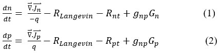
In these equations, ∇ ⃑.Jn˜ is the divergence of electron current density, ∇ ⃑.Jp˜ is the divergence of hole current density, n corresponds to the densities of electrons, and p represents the densities of holes. The Langevin recombination rate is denoted by RLangevin, while the corresponding recombination rates are indicated by Rnt and Rpt. The final terms in equations (1) and (2) account for optical charge generation, where gnp corresponds to the generation efficiency. These equations describe the behaviour of charge carriers and are coupled with Poisson’s equation.
![]()
Here, q is the elementary charge, ε is the relative permittivity, and ε0 is the vacuum permittivity, p and n are the free hole and electron concentration, pt is the trapped hole concentration, nt is the trapped electron concentration, E˜ represents the electric field, and Adoping and Ddoping represent the acceptor and donor doping concentrations, respectively.
The Langevin recombination model describes the bimolecular recombination process in organic semiconductors (RLangevin), given by
![]()
The mobilities of electrons (μₙ) and holes (μₚ), as well as the concentrations of local charge carriers dictate the Langevin recombination rate. In this case, η is the Langevin recombination process efficiency and ni is the intrinsic carrier concentration at thermal equilibrium.
The trap rate equation, which simulates the exchange of trapped carriers with energy levels in the organic semiconductor, describes the processes of trapping and de-trapping. For example, an electron trap interacts with the Highest Occupied Molecular Orbital (HOMO) and Lowest Unoccupied Molecular Orbital (LUMO), the levels at rates and , respectively, facilitating the exchange of electrons or holes27.
![]()
This equation describes Shockley–Read–Hall (SRH) recombination, a process in which free electrons are captured by traps and then recombine with free holes.
These simulations highlight the significant impact of the electrode work function on the performance metrics of organic solar cells. The results highlight how proper energy level alignment at the electrode interfaces minimises charge extraction barriers and recombination losses, thereby enhancing the power conversion efficiency (PCE) and fill factor (FF). This emphasises the pivotal role of electrode work function engineering in optimising device performance and guiding the design of high-efficiency, scalable organic solar cells.
Material and Methods
The electrical parameters employed in our simulations for the ITO/PEDOT: PSS2/DPPEZnP-TBO2/ ZnO /PEDOT: PSS1/DPPEZnP-TBO1/Al structure are presented in Figure 1(a). We simulated the performance of an organic solar cell with the following layer structure: ITO, PEDOT: PSS, DPPEZnP-TBO, ZnO, PEDOT: PSS, DPPEZnP-TBO, and aluminium (Al). In this configuration, ITO and PEDOT: PSS serve as the front electrode, while Al serves as the back electrode. The cell’s performance was evaluated using both flexible and rigid substrates. In this tandem OSC structure, ITO/PEDOT: PSS2/DPPEZnP-TBO2/ZnO forms the front cell, while PEDOT: PSS1/DPPEZnP-TBO1/Al constitutes the rear cell. The two sub-cells are connected through the ZnO/PEDOT: PSS1 interlayer, enabling efficient charge recombination and current matching. PEDOT: PSS layers act as charge transport and interface modification layers with position-dependent functions. PEDOT: PSS2 (near ITO) serves as a hole transport and anode buffer layer, enhancing ITO’s work function and facilitating hole extraction. PEDOT: PSS1 (between ZnO and DPPEZnP-TBO1) operates as an interfacial recombination layer in the tandem structure. It enables efficient charge recombination and ensures proper energy alignment, thereby improving device performance.
DPPEZnP-TBO2 and DPPEZnP-TBO1 are abbreviated as layer 2 and layer 1, respectively, which act as an active layer. Figure 1(b) illustrates the energy band alignment of the layers in the organic solar cell. It includes the energy band gap values for PEDOT: PSS, DPPEZnP-TBO, and ZnO. This alignment is crucial for understanding charge transport and efficiency in the device. DPPEZnP-TBO serves as the active layer, responsible for photon absorption, charge separation, and conducting charges to the electrodes. These include crucial measurements including fill factor (FF), power conversion efficiency (PCE), open-circuit voltage (VOC), and short-circuit current density (JSC). Table 2 displays the material characteristics used in the simulation of tandem organic solar cell architectures28-30.
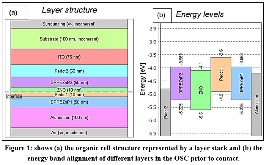 |
Figure 1: shows (a) the organic cell structure represented by a layer stack and (b) the energy band alignment of different layers in the OSC prior to contact. Click here to View Figure |
Table 2: Simulation input parameters corresponding to the materials in tandem organic solar cell structures.
| Terms | DPPEZnP-TBO | ZnO | PEDOT: PSS |
| Bandgap | 1.262 | 1.5 | 1.3 |
| Dielectric constant | 6.51 | 9 | 2.7 |
| Mobility (μe) | 7.5 /Vs | /Vs | /Vs |
| Mobility (μp) | /Vs | /Vs | /Vs |
| Anions (µe * id) | 1 /Vs | 0.01 /Vs | 1 /Vs |
| Cations (µp * id) | 1 /Vs | 0.0025 /Vs | 1 /Vs |
| Recombination efficiency | 0.08 | 1 | 0.001 |
| 3 | 1 | 1 |
Results and Discussions
Charge Dynamics
Figure 2(a) presents a schematic energy level diagram illustrating the energy levels of a semiconductor in contact with electrodes. The LUMO, HOMO, electron Fermi levels, and hole Fermi levels are represented by the colours red, blue, green, and violet, respectively. It draws attention to the Fermi energy levels for electrons (EFn) and holes (EFp), as well as the Lowest Unoccupied Molecular Orbital (LUMO) and Highest Occupied Molecular Orbital (HOMO). When a semiconductor interacts with electrodes, its energy levels align relative to the electrodes’ Fermi levels31. This alignment governs charge carrier (electron and hole) movement and significantly impacts the semiconductor’s electrical properties, such as current conduction and junction characteristics. The diagram provides a clear visual representation of these energy levels and their interactions, offering insights into the semiconductor’s behaviour with electrodes. In organic semiconductors, charge transport primarily occurs through thermally assisted tunnelling, also known as hopping, between individual molecules32. This involves thermally activated tunnelling, where thermal energy helps carriers overcome energy barriers between adjacent molecules. Figure 2(a) also demonstrates how the HOMO, LUMO, and Fermi energy levels change layer by layer. As the barrier potential between the layers decreases, the contact type transitions from non-Ohmic to Ohmic. In organic solar cells, the interface between the electrode and the active layer plays a crucial role in charge transport33. Ohmic contacts are formed when the electrode’s work function aligns closely with the HOMO (for hole transport) or the LUMO (for electron transport) of the organic material, enabling efficient charge flow and minimising energy loss. Conversely, non-Ohmic contacts result from significant energy barriers, which hinder charge transfer and reduce performance. Electrodes with low work functions (e.g., aluminium) are well-suited for electron transport through the LUMO. In contrast, high work function materials (e.g., gold or ITO with PEDOT: PSS) align better with the HOMO for hole transport34. By carefully selecting electrode materials to match their work functions with the active layer’s energy levels, barriers can be minimised, leading to Ohmic contacts and enhanced efficiency in organic solar cells. The colour diagram, visually shown in figure 2 (b) the variation in energy levels, highlighting distinct phases of charge transport. The colour gradients in the diagram indicate transitions between HOMO, LUMO, EFn, and EFp, emphasising the alignment or misalignment of energy levels across layers.
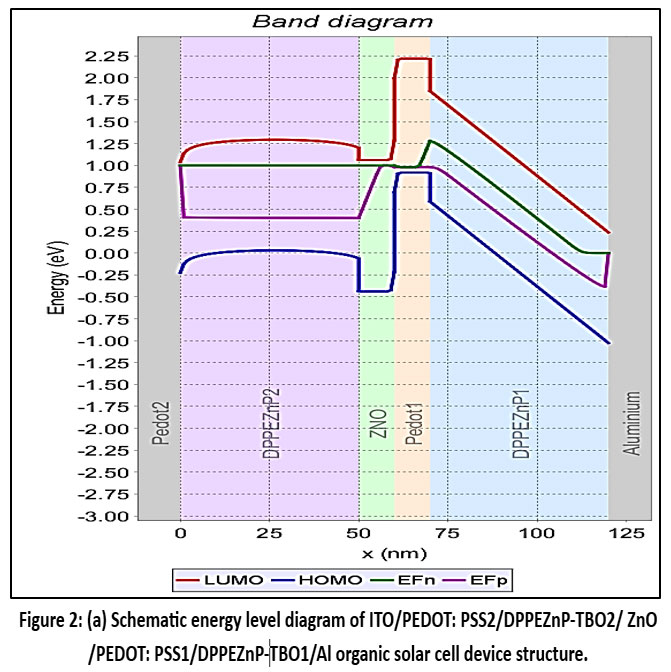 |
Figure 2(a): Schematic energy level diagram of ITO/PEDOT: PSS2/DPPEZnP-TBO2/ ZnO /PEDOT: PSS1/DPPEZnP-TBO1/Al organic solar cell device structure. Click here to View Figure |
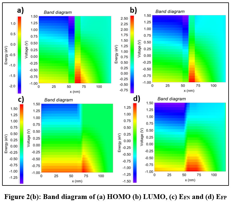 |
Figure 2(b): Band diagram of (a) HOMO (b) LUMO, (c) EFN and (d) EFP Click here to View Figure |
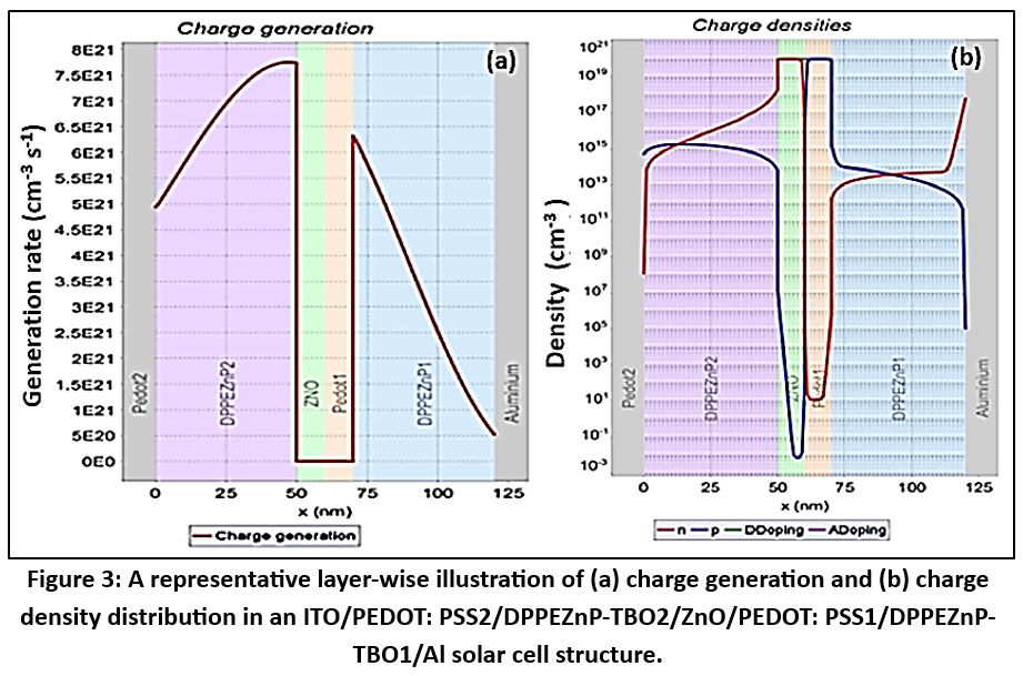 |
Figure 3: A representative layer-wise illustration of (a) charge generation and (b) charge density distribution in an ITO/PEDOT: PSS2/DPPEZnP-TBO2/ZnO/PEDOT: PSS1/DPPEZnP-TBO1/Al solar cell structure. |
Figure 3 presents a layer-wise representation of (a) charge generation and (b) charge density distribution within the ITO/PEDOT: PSS2/DPPEZnP-TBO2/ ZnO /PEDOT: PSS1/DPPEZnP-TBO1/Al solar cell structure. The ITO layer acts as the transparent conductive electrode, enabling light to pass through to the active layers without significant charge generation. PEDOT: PSS2 Layer acts as the hole transport layer, as well as improves the work function matching between the ITO electrode and the DPPEZnP-TBO2 layer. Charge generation here is minimal due to its primary role in facilitating hole extraction rather than light absorption. The DPPEZnP-TBO (DPPEZnP2) layer is the first active layer where light absorption begins. Charge generation starts increasing and remains high. The ZnO Layer acts as the electron transport layer. Charge generation in this layer is very low, as it primarily facilitates electron mobility rather than light absorption. DPPEZnP-TBO (DPPEZnP1) Layer is the second active layer, where the significant light absorption occurs. Charge generation is moderate in this layer due to its optimised properties for absorbing photons and generating charge carriers. Charge generation decreases linearly from the DPPEZnP1 layer towards this layer, as fewer photons remain to be absorbed. The Aluminium Layer serves as the back electrode for charge collection.
In Figure 3(b), the charge density is higher in both active layers (DPPEZnP-TBO). The ZnO layer shows the highest electron density, while the PEDOT: PSS1 layer shows the highest hole density. Since the ZnO layer acts as the electron transport layer, it efficiently facilitates electron movement toward the electrode.
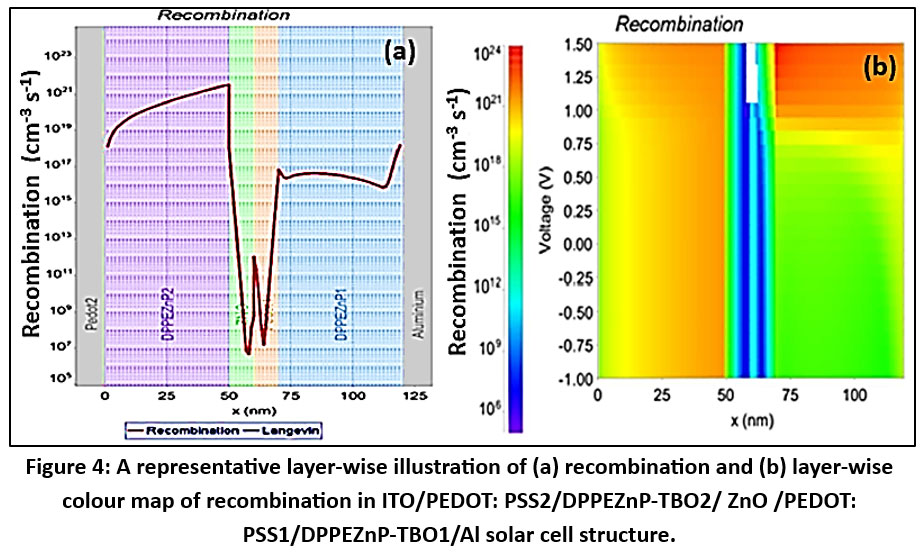 |
Figure 4: A representative layer-wise illustration of (a) recombination and (b) layer-wise colour map of recombination in ITO/PEDOT: PSS2/DPPEZnP-TBO2/ ZnO /PEDOT: PSS1/DPPEZnP-TBO1/Al solar cell structure. |
Figure 4 provides a layer-wise illustration of (a) recombination and (b) layer-wise distribution of recombination using a colour map within the ITO/PEDOT: PSS2/DPPEZnP-TBO2/ ZnO /PEDOT: PSS1/DPPEZnP-TBO1/Al solar cell, highlighting regions of charge carrier loss. These results help to identify how the layers impact device performance. The recombination rate is significantly high in the DPPEZnP-TBO layers (active layers), where most charge generation occurs, leading to greater carrier interactions. In contrast, recombination is minimal in the ZnO and PEDOT: PSS layers due to their transport-dominated roles. Figure 4(b) shows that the highest recombination occurs in the range of thickness from 0 to 50 nm and 70 to 125 nm. When PEDOT: PSS serves as the electrode, carrier recombination significantly impacts key performance metrics.
Diffusion-driven carriers may recombine before reaching the contacts, resulting in a slight reduction in the short-circuit current density (JSC)35. Under open-circuit conditions, carrier accumulation at the electrodes creates a potential difference defining the open-circuit voltage (VOC)36. Recombination narrows the separation between the electron and hole quasi-Fermi levels (EFn and EFp), lowering VOC. The PEDOT: PSS work function strongly influences recombination rates and overall performance, as a stronger electric field across the absorber enhances charge separation and reduces recombination.
 |
Figure 5: Current vs voltage characteristics of OSC with different work functions. Click here to View Figure |
Current density (J) vs voltage (V) Analysis
Figure 5 presents the current density (J) vs voltage (V) characteristics of an ITO/PEDOT: PSS2/DPPEZnP-TBO2/ ZnO /PEDOT: PSS1/DPPEZnP-TBO1/Al organic solar cell. The J-V characteristics of organic solar cells (OSC) are strongly influenced by the work function of the electrodes because the work function determines the energy alignment between the electrodes and the organic material layers37. The work function is the energy required to move an electron from the electrode into the vacuum level, and this alignment plays a crucial role in charge injection and extraction. The work function of the electrode affects the ability of the electrode to inject charge carriers (electrons or holes) into the organic layers38. For efficient charge injection, the electrode’s work function must align with the energy levels of the organic material’s conduction or valence bands (LUMO for electrons, HOMO for holes). If the electrode’s work function is too high or too low compared to the organic material’s energy levels, a significant energy barrier forms, hindering charge injection39. After charge carriers are generated in the organic material by light absorption, they must be extracted by the electrodes. The electrode work function influences how easily charge carriers are extracted from the organic layer. If the electrode’s work function is well-matched with the energy levels of the organic layer, charge extraction is efficient, and the J-V characteristics improve.
As shown in Figure 6, the open-circuit voltage (VOC) increases with the PEDOT: PSS work function after it exceeds 4.2 eV, reaching a stable value of approximately 0.56 V. In contrast, the short-circuit current density (JSC) follows the same trend. The JSC value stabilises up to a work function of 4.4 eV, but beyond this point, it increases rapidly. In organic solar cells, the electrical properties are highly dependent on the energy level alignment between the electrode materials and the organic layers. As the PEDOT: PSS work function increases, the alignment between the electrode and the active layer improves, leading to a higher VOC due to better charge separation. JSC increases with increasing work function because a higher work function improves charge extraction by reducing the energy barrier at the electrode–active layer interface38.
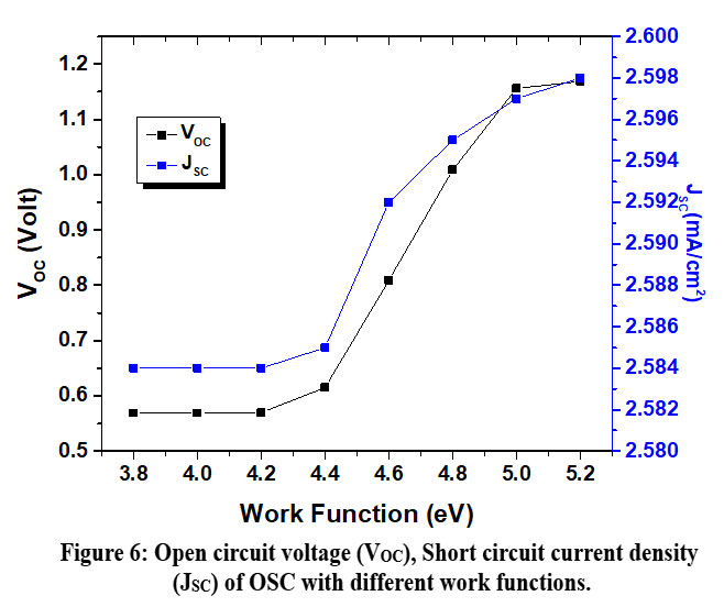 |
Figure 6: Open circuit voltage (VOC), Short circuit current density (JSC) of OSC with different work functions. Click here to View Figure |
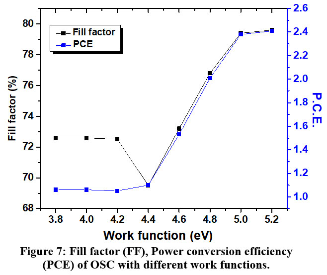 |
Figure 7: Fill factor (FF), Power conversion efficiency (PCE) of OSC with different work functions. Click here to View table |
Figure 7 shows that the fill Factor (FF) and power conversion efficiency (PCE) of an Organic Solar Cell (OSC) with varying anode work functions. Figure 7 shows that increasing the anode work function raises the hole density at the ITO/PEDOT: PSS interface (x = 0), thereby lowering the contact resistance. This inverse correlation between contact resistance and charge density at the electrode interface aligns with findings from previous studies41. Consequently, a reduction in series resistance is observed, leading to an improvement in the fill factor as the anode work function increases, thereby enhancing charge carrier extraction and overall device performance. The graph also shows the correlation between fill factor (FF) and power conversion efficiency (PCE) of the Organic Solar Cell (OSC) at different work function values. For work functions up to 4.4 eV, both the efficiency and fill factor remain stable, indicating consistent performance. Beyond 4.4 eV, both parameters increase linearly, suggesting that higher work functions further enhance charge carrier extraction and improve the device’s overall performance.
Conclusions
This study designs and analyses a planar ITO/PEDOT: PSS2/DPPEZnP-TBO2/ ZnO /PEDOT: PSS1/DPPEZnP-TBO1/Al organic solar cell using SETFOS to examine the effect of PEDOT: PSS electrode work function. Results show that optimising work function alignment between front and rear electrodes significantly impacts VOC, JSC, and FF, highlighting its crucial role in improving DPPEZnP-TBO tandem OSC performance. By varying the work function, both VOC and JSC were observed to change significantly with an increase in the work function. The best performance was achieved at a work function of 5.2 eV, resulting in a VOC of 1.16 V, JSC of 2.598 mA/cm², FF of 79.6%, and a power conversion efficiency (PCE) of 2.41%. These results suggest that optimising the electrode work function enhances charge mobility, minimises recombination losses, and improves overall device performance. This study offers key insights for enhancing the efficiency, stability, and scalability of DPPEZnP-TBO organic solar cells, supporting their potential for large-scale solar energy applications.
Acknowledgement
The authors would like to acknowledge Laxmi Narayan Dubey College, Motihari, and B.R. Ambedkar Bihar University, Muzaffarpur, for providing the simulation software, Fluxim-SETFOS.
Funding Sources
The author(s) received no financial support for the research, authorship, and/or publication of this article
Conflict of Interest
The authors do not have any conflict of interest
Data Availability Statement
This statement does not apply to this article
Ethics Statement
This research did not involve human participants, animal subjects, or any material that requires ethical approval
Informed Consent Statement
This study did not involve human participants, and therefore, informed consent was not required
Author Contributions
Pinaki Laha: Writing – review and editing, Writing – original draft, Methodology, Investigation, Formal analysis, Data curation, Validation, Software.
Sanjay Narayan Barman: Investigation, Formal analysis, Data curation, Validation, Software.
References
- Nkinyam CM, Ujah CO, Nnakwo KC, Kallon DVV. Insight into organic photovoltaic cell: prospects and challenges. Unconv Resour. 2025;5:100121. doi:10.1016/j.uncres.2024.100121
CrossRef - Ujah CO, Kallon DVV, Aikhuele DO, Aigbodion VS. Advanced composite materials: a panacea for improved electricity transmission. Appl Sci. 2022;12:8291. doi:10.3390/app12168291
CrossRef - Shukla A, Shrivastava PK, Sharma P, Sharma AK. Experimental investigations on a hybrid solar assisted phase change enhanced liquid desiccant cooling system. Energy Sources Part A Recovery Utilization and Environmental Effects. 2025;47(1):21-43. doi:10.1080/15567036.2024.2438945
CrossRef - Jani DB. Performance assessment of solar powered hybrid solid desiccant and dehumidification integrated thermally cooling system using TRNSYS. In: Advances in Clean Energy Technologies. Academic Press; 2021:171-203. doi:10.1016/B978-0-12-821221-9.00004-9
CrossRef - Zhang MMKS, Cho HH, Yum JH. Recent advances in organic photovoltaic materials and device architectures. Adv Energy Mater. 2022;12:2202363. doi:10.1002/aenm.202202363
CrossRef - Riede M, Spoltore D, Leo K. Organic solar cells—The path to commercial success. Adv Energy Mater. 2021;11:2002653. doi:10.1002/aenm.202002653
CrossRef - Vlasov AS, Afanasev KM, Galimov AI, et al. Influence of interface states on charge transport in organic semiconductor structures. Semiconductors. 2024;58:187-190. doi:10.1134/S1063782624020167
CrossRef - Qasim S, Abdul Ameer F. Charge carrier recombination mechanisms in polymer-based optoelectronic devices. Semiconductors. 2025;59:507-512. doi:10.1134/S1063782625600342
CrossRef - Song W, Peng R, Huang L, et al. Over 14% efficiency folding-flexible ITO-free organic solar cells enabled by eco-friendly acid-processed electrodes. iScience. 2020;23:100981. doi:10.1016/j.isci.2020.100981
CrossRef - Zhao C, Tang CG, Seah ZL, et al. Improving organic photovoltaic cells by forcing electrode work function well beyond onset of ohmic transition. Nat Commun. 2021;12:2250. doi:10.1038/s41467-021-22358-y
CrossRef - Kawano K, Ito N, Nishimori T, Sakai J. High-performance bulk heterojunction organic solar cells using poly(3-hexylthiophene) and fullerene derivatives. Appl Phys Lett. 2006;88:073514. doi:10.1063/1.2177633
CrossRef - Shrotriya V, Wu EH, Li G, Yao Y, Yang Y. Efficient light harvesting in multiple-device stacked structure for polymer solar cells. Appl Phys Lett. 2006;88:064104. doi:10.1063/1.2172741
CrossRef - Gilot J, Wienk MM, Janssen RAJ. Double and triple junction polymer solar cells processed from solution. Appl Phys Lett. 2007;90:143512. doi:10.1063/1.2345612
CrossRef - Kim JY, Lee K, Coates NE, et al. Efficient tandem polymer solar cells fabricated by all-solution processing. Science. 2007;317:222-225. doi:10.1126/science.1141711
CrossRef - Li M, Gao K, Wan X, et al. Solution-processed organic tandem solar cells with power conversion efficiencies over 12%. Nat Photonics. 2017;11:85-90. doi:10.1038/nphoton.2016.240
CrossRef - Fan X, Stott NE, Zeng J, et al. Efficient and stable organic solar cells enabled by interfacial energy level modulation. J Mater Chem A. 2023;11:18561-18570. doi:10.1039/D3TA03213B
CrossRef - Hu L, Song J, Yin X, Su Z, Li Z. Research progress on polymer solar cells based on PEDOT: PSS electrodes. Polymers. 2020;12:145. doi:10.3390/polym12010145
CrossRef - Yu Z, Xia Y, Du D, Ouyang J. PEDOT: PSS films with enhanced conductivity via post-treatment for flexible electronics. ACS Appl Mater Interfaces. 2016;8:11629-11638. doi:10.1021/acsami.6b00317
CrossRef - Li Z, Liang Y, Zhong Z, et al. Highly conductive and transparent PEDOT: PSS films for optoelectronic applications. Synth Met. 2015;210:363-370. doi:10.1016/j.synthmet.2015.11.006
CrossRef - Zhou Y, Cheun H, Choi S, Fuentes-Hernandez C, Kippelen B. Indium tin oxide-free and metal-free semitransparent organic solar cells. Science. 2011;332:316-319. doi:10.1126/science.1218829
CrossRef - Ouyang J. Solution-processed PEDOT:PSS films with conductivity enhancement for organic electronics. Displays. 2013;34:5-9. doi:10.1016/j.displa.2013.08.007
CrossRef - Chang YM, Wang L, Su WF. Improving the efficiency of polymer solar cells using modified buffer layers. Org Electron. 2008;9:968-973. doi:10.1016/j.orgel.2008.07.003
CrossRef - Li Z, Qin F, Liu T, et al. Interface engineering for high-performance inverted polymer solar cells. Org Electron. 2015;21:1-8. doi:10.1016/j.orgel.2015.01.012
CrossRef - Fluxim AG. SETFOS, version 5.5. Switzerland; 2023. Accessed 2023. https://www.fluxim.com
- Feron K, Belcher WJ, Fell CJ, Dastoor PC. Organic solar cells: understanding the role of interlayers. Int J Mol Sci. 2012;13:17019-17047. doi:10.3390/ijms131217019
CrossRef - Salem MS, Shaker A, Abouelatta M, Saeed A. Performance enhancement of organic solar cells using interface engineering. Polymers. 2023;15:784. doi:10.3390/polym15030784
CrossRef - Neukom M. Comprehensive Characterisation and Modelling of Operation Mechanisms in Third Generation Solar Cells. Augsburg, Germany: University of Augsburg; 2019.
- Li XD, Chen TP, Liu P, Liu Y, Liu Z, Leong KC. Electrical characterization of organic semiconductor devices using impedance spectroscopy. J Appl Phys. 2014;115:1-6. doi:10.1063/1.4868338
CrossRef - Jan H, Mathew S, Bhotla PV. Interface-dependent charge transport in organic electronic devices. ACS Appl Electron Mater. 2024. doi:10.1021/acsaelm.4c01098
CrossRef - Rawat M, Laha P. Charge transport modeling in organic thin-film devices. Bull Mater Sci. 2025;48:112. doi:10.1007/s12034-025-03466-7
CrossRef - Gobbi M, Pietrobon L, Atxabal A, et al. Charge injection and transport in organic semiconductors probed by magnetoresistance. Nat Commun. 2014;5:4161. doi:10.1038/ncomms5161
CrossRef - Coropceanu V, Cornil J, da Silva Filho DA, Olivier Y, Silbey R, Brédas JL. Charge transport in organic semiconductors. Chem Rev. 2007;107:926-952. doi:10.1021/cr050140x
CrossRef - Rahimi R, Roberts A, Narang V, Kumbham VK, Korakakis D. Optical modeling of multilayer organic optoelectronic devices. Opt Mater. 2013;35:5-11. doi:10.1016/j.optmat.2012.12.011
CrossRef - Yi C, Hu X, Gong X, Elzatahry A. Interface and morphology control in organic optoelectronics. Mater Today. 2016;19:3-10. doi:10.1016/j.mattod.2015.11.003
CrossRef - Sherkar TS, Momblona C, Gil-Escrig L, et al. Recombination mechanisms in perovskite and organic solar cells. ACS Energy Lett. 2017;2:1214-1222. doi:10.1021/acsenergylett.7b00236
CrossRef - Li C, Lv L, Qin L, et al. Influence of interfacial layers on organic photovoltaic performance. Materials. 2018;11:2407. doi:10.3390/ma11122407
CrossRef - Khalf A, Gojanovic J, Cirovic N, Zivanovic S, Matavulj P. Numerical modeling of organic solar cell devices. IEEE J Photovolt. 2020;10:1-8. doi:10.1109/JPHOTOV.2020.2965401
CrossRef - Lee H, Cho SW, Park SH, Cho MH, Yi Y. Interface engineering in organic optoelectronic devices. Mater Res Bull. 2014;58:19-23. doi:10.1016/j.materresbull.2014.05.010
CrossRef - Lee JH, Kim JJ. Charge injection and transport in organic light-emitting devices. Phys Status Solidi A. 2012;209:8-14. doi:10.1002/pssa.201228199
CrossRef - Shuttle CG, Hamilton R, O’Regan BC, Nelson J, Durrant JR. Charge-density dependence of open-circuit voltage in organic solar cells. Proc Natl Acad Sci U S A. 2010;107:16448-16452. doi:10.1073/pnas.1004363107
CrossRef - Tan JK, Png RQ, Zhao C, et al. Trap-assisted recombination in organic semiconductor devices. Nat Commun. 2018;9:3269. doi:10.1038/s41467-018-05200-w
CrossRef
Accepted on: 26 Dec 2025
Second Review by: Dr. D. B. Jani
Final Approval by: Dr. Shouxun Ji


![]()
![]()
![]()
![]()