Recent Trends in Flexible Nanogenerators: A Review
Ömer Faruk Ünsal and Ayşe Çelik Bedeloğlu*
Department of Fiber and Polymer Engineering, Bursa Technical University, Bursa, Turkey, 16310,
Corresponding Author Email: ayse.bedeloglu@btu.edu.tr
DOI : http://dx.doi.org/10.13005/msri/150202
Download this article as:
![]()
Harvesting energy from environment presents a remarkable practical way to supply energy for smart self-powered advanced devices such as remote sensing devices, wireless networks, biomedical and wearable devices. A nanogenerator converting mechanical/thermal energy into electricity is an interesting emerging technology since it produces energy from environment. The nanogenerators have different energy production approaches about which many significant studies are going on. In recent years, technological and scientific researches have been focused on flexible devices to increase the application fields. Besides, increasing work on nanogenerators showed that providing flexibility to these devices will contribute to producing more ergonomic smart systems. The devices, which are capable to be used in textile, medical, mechanical etc. industries are also designed especially in academic studies. In this review, recent trends in the field of flexible nanogenerators were presented by demonstrating new potential applications in different areas.
KEYWORDS:Flexible nanogenerators; Piezoelectric; Triboelectric; Pyroelectric; Self-Powered; Nanofiber; Textile; Wearable
Introduction
Ongoing national and international problems related to production, transportation, usage and conservation of energy and increasing serious environmental problems caused by use of conventional energy resources like fossil fuels etc. threaten sustainable development of modern life. Implementing stabilized, enduring and innovative energy policies is important for economic and social development in worldwide.
Renewable energy technologies such as hydropower, geothermal, wind, and solar energies are clean sources of energy and have a much lower environmental impact than conventional energy technologies as well as play an important role in reducing greenhouse gas emissions causing global warming.
On the other hand, with the growing development of nanotechnology-based devices, researchers and companies have concerns about power supply. Since especially micro/nano scale devices or systems become more important in wearable and implantable devices, power providers came to the agenda. Furthermore, self-powered and sustainable devices are preferred than the systems with conventional batteries.
In recent years, nanogenerators have attracted considerable great attention, since those devices are able to produce low-cost, clean, efficient and sustainable energy by harvesting energy from environment.1 Nanogenerators are structures that convert mechanical or thermal energy into electrical energy with small physical interactions.2 In addition, these devices are very convenient to build a system that generates their own energy when integrated into functional devices thanks to their nano/micro dimensions.3
Flexible Nanogenerators for Energy Harvesting
Nanogenerators mainly use three type approaches including triboelectric, piezoelectric and pyroelectric. Nanogenerators have added a new dimension to the principles of converting mechanical energy into electrical energy using piezoelectric and triboelectric effects. Additionally, some devices used to convert thermal energy into electricity with pyroelectric effect. It was reported that the piezoelectric systems perform better than triboelectric ones.4
There is a trend on nanogenerator researches; provide flexible property on these devices. Waste energy usually goes to be waste as multi-axially due to nature of waste mechanical energy. For example, joint, knee, finger movements; centrifugal force, stretching and compressing movement on mechanics are most common examples for multi-axial waste energy. Nanogenerators that is aiming to capture this multi-axial mechanical energy should be flexible.
Polymers, due to their stretchable characteristic and mechanical stability are preferred to produce nanogenerators. Polymers are used by two ways on nanogenerators. The first; polymers have been used as matrix in nanocomposite generators. The second way; piezoelectric polymers have been used to produce polymeric flexible nanogenerators.5 Highest output values are approximately 500 V and 5.3 mA for triboelectric nanogenerators6; 200 V and 1.5 µA for piezoelectric nanogenerators.7
Piezoelectric Nanogenerators (PENGs)
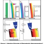
When a piezoelectric material is subjected to a mechanical action, the net positive and net negative charges resulting from the collection of the load carriers on their surface will provide an electrical stress (Figure 1). Similarly, when a piezoelectric material is subjected to electrical voltage change, it deforms mechanically.8 The piezoelectric effect is usually defect in crystal structures due to a molecular symmetric centre. It is evident that the piezoelectric effect is observed by means of opposing poles deposited in amorphous regions in polymers.9
Besides, the electronic differences of the atoms in the polymer chains cause the piezoelectric effect. Fukada, for example, explained in 1974 that he observed the piezoelectric effect in biopolymers, both in the form of β and in the form of α-helix. Here, the atomic composition of the polymer causes the formation of chiral carbon atoms in the polymer backbone, which leads to an electrical gradient.10
Figure 1: Working Principle of Piezoelectric Nanogenerators.8
|
|
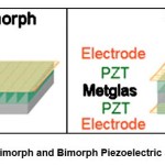
Both the threshold value and the energy produced are the levels that can be used directly in the piezoelectric effect. Another advantage of the piezoelectric method is that it can be produced and operated in both macro and micro dimensions.11-13 The magnitude and direction of the piezoelectric effect is also parallel to the magnitude and direction of the mechanical force loaded. Among the various piezoelectric nanogenerator structures, unimorph and bimorph (Figure 2) type cantilevered beams are the simplest.14
Figure 2: Unimorph and Bimorph Piezoelectric Structures.15
|
|
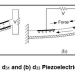
Cantilevered beam type piezoelectric nanogenerators can produce electricity in d33 and d31 piezoelectric production modes. Here, “d” represents the piezoelectric constant of the material, and “31” or “33” represents the method of polarizing the material.16 As seen in Figure 3, the d31 mode electrodes are perpendicular to the polarization direction; In the d33 mode, the electrodes have the same polarity direction.17
Figure 3: (a) d31 and (b) d33 Piezoelectric Designs.17
|
|
The alternating current generated by the piezoelectric nanogenerators must go through the rectifier and be stored in the supercapacitor in order to be usable. So an AC-to-DC conversion is necessary.18
Another factor that is directly related to the performance of these devices is modeling. Because the performance of a nanogenerator is primarily due to the piezoelectricity of the piezoelectric layer; Secondly, it is shaped parallel to the electrical resistance of the external components.19
The crystals are usually piezoelectric materials and generally piezoelectric nanowires are placed on a vertically conductive surface. This is accomplished by chemical vapour deposition (CVD), inductively coupled plasma (ICP) deposition, and chemical solution methods. With the nanowire grown by the CVD method, the initiators are attached to the surface so that the piezoelectric material to be used can grow. Subsequently, the base material of nanowire is atomized with high heat and sent to the surface (Figure 4). The particles sent to the surface are held only by the regions where the initiators are, and the nanowires are grown on the surface. It has recently been preferred to carry out the enlargement process using the electric field and in solution after the same seeding process.20
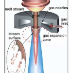
In the ICP method, as in CVD, the piezoelectric material is brought to the vapour phase; followed by passing through an induction coil with a high voltage applied and sent to the surface and nanostructures are grown (Figure 5).
Figure 4: Film Creation Mechanism by CVD Method.21
|
|
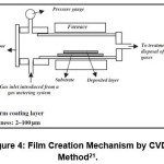
Figure 5: ICP Material Storage System.22
|
|
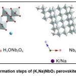
Compounds that has ABO3 formula are named as perovskites. Nowadays, nanoparticles of perovskite crystals were preferred on nanogenerator studies due to their dielectric properties. BaTiO3, Pb(Zr,Ti)O3 and (K, Na)NbO3 nanocrystals like nanorods, nanowires, nanobelts etc. are most commonly used perovskite piezoelectric materials.23,24 These nanostructures were usually synthesized by hydrothermal method and molten salt method (Figure 6).
Figure 6: Formation steps of (K,Na)NbO3 perovskite crystals.25
|
|
Although nanostructure based nanogenerators have mechanical flexibility with small defects in their structures, most of the materials used are expensive because of their difficult and complicated manufacturing conditions, also brittle and not efficient in case of large scale applications due to low power output.16
Polymers having piezoelectric effect are good alternatives to inorganic ones with their good mechanical flexibility. Additionally, polymer-based nanogenerators are suitable for low weight applications.16
Bulk piezoelectric polymers (PVDF and PVDF copolymers, Parylene-C and Amorphous polyimide) are widely used. PVDF is the most commonly used piezopolymer since it has the largest piezoelectric coefficient (20–28 pC N-1) among other bulk polymers. Although PVDF have five different polymorphs of β, α, γ, δ, and ɛ, mostly, α, β and γ phases are studied.16
Recently, nanofiber structures obtained by PVDF electro-production method have started to be preferred in piezoelectric nanogenerators. PVDF can be used in nanofiber nanogenerators due to its electronic properties and the mechanical strength of the polymer construction. The non-polarized alpha phase of the PVDF nanofibers turns to the polarized beta phase with high electric field effect. In this way PVDF nanofiber is used as a piezoelectric layer in nanogenerators. The linear mechanical effect exerted on the PVDF piezoelectric layer reveals a voltage opposite to that of the characteristic piezoelectric charge of PVDF (-) opposite to that of the polarity.26
These new piezoelectric nanogenerators are a versatile electricity generation strategy that collects environmental waste energy for potential practical applications. Nanogenerators are particularly promising for miniaturization of more powerful packages than their implications for biological detection, environmental monitoring and personal electronics, and their powerful nanosystems. In particular, flexible and collapsible Nanogenerators are useful in areas having special mechanical and structural requirements, such as muscle or joint implanted biosensors. However, although there are many studies about electrospun PVDF nanofibres/nanofibre mats27-33 there are still challenges related to low output power due to phase content of PVDF, high electrical resistance and lower surface charge density in and over the nanofibres, respectively.
Lin et al have produced a flexible and transparent piezoelectric nanogenerator. ZnO nanowires on PDMS were grown in solution. Piezoelectric film is coated with PMMA through the surface of the nanotubes. Top and bottom faces of the film were then coated with ITO to serve as electrodes. A voltage of 8V was obtained from the device.34
In another study35 formamidium lead halide perovskite(FAPbBr3) which is a piezoelectric material dominantly was used as “piezoelectric reinforcing material” in a piezoelectric matrix. FAPbBr3 nanoparticles were added into PVDF in different concentrations (6-9-12-15-18 %wt). Nanocomposite solution was poured onto a glass substrate. And then annealed 2 hours at 80°C and 2 hours at 130°C to dominate the β phase PVDF. PET foils are deposited with Cr (10 nm) and Au(90 nm) to form top and bottom electrodes of nanogenerator. PET/Cr/Au electrodes were integrated to piezoelectric layer and the nanogenerator was kept under an electric field of 50 kV/cm for 1 hour. Piezoelectric nanocomposite was characterized by fourier transform infrared spectrum analysis. Absorption peaks of analysis at 840 cm-1 and 1275 cm-1 were shown the β phase domination of PVDF after thermal treatment. Piezoelectric voltage and current outputs of nanogenerators were measured under compress/release process with 0.5 MPa at frequency of 5 Hz. 12 %wt nanocomposite was shown the best piezoelectric performance with 30 V.
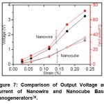
Jung et. al. has been manufactured a piezoelectric nanogenerator based on piezoelectric perovskite nanocomposite.36 NaNbO3 nanowires and nanocubes were synthesized by hydrothermal method. Nanowires and nanocubes were mixed with PDMS resin with %1 volume ratio. Then nanocomposite solution was spin coated on Au/Cr coated polyimide film and another Au/Cr coated polyimide film integrated with nanocomposite/electrode polyimide film to form the nanogenerator. As a last step, sandwiched nanocomposite is attached to a polyester film. 80 V/cm electric field and a periodic bending force were applied to the piezoelectric nanocomposite. Nanowire based device has shown better performance than nanocube based nanogenerator with 3.2 V and 72 nA (figure 7).
Figure 7: Comparison of Output Voltage and Current of Nanowire and Nanocube Based Nanogenerators.36
|
Click on image to enlarge |
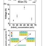
In a similar study, zinc stannat nanocubes were mixed with PDMS with different concentrations. PDMS/ZnSnO3 solution was spin coated onto indium tin oxide coated polyethylene naphthalate. Nanocomposite surface of film was coated with 10 nm thick Cr and 100 nm thick Au. The best performance among nanogenerators under %0.91 vertical compress strain was shown by %40 wt. nanocomposite (12 V and 0.9 µA)(Figure I).
In a similar study, zinc stannat nanocubes were mixed with PDMS with different concentrations37. PDMS/ZnSnO3 solution was spin coated onto indium tin oxide coated polyethylene naphthalate. Nanocomposite surface of film was coated with 10 nm thick Cr and 100 nm thick Au. The best performance among nanogenerators under %0.91 vertical compress strain was shown by %40 wt. nanocomposite (12 V and 0.9 µA)(Figure 8).
Figure 8: a) Output current and voltage of ZnSnO3:PDMS with %40 concentration. b) Output voltage comparison with ZnSnO3 concentration. c) Output piezoelectric potential distribution of HP-NG with different ZnSnO3 concentration.37
|
|
Fuh and Wang used polyvinylidene fluoride (PVDF), which is a dielectric material with high dielectric properties, as a piezoelectric layer by electrospinning in the form of nanofibers. Nanofibers are produced in parallel with each other by electrospinning in the near field (1-2 mm). It has been determined that the performance of the obtained nanogenerator is improved in this way.38 Produced nanogenerators were used to electrically identify some human gestures.
In a study conducted in 2017, PVDF electrospinning method was used to produce a 200 μm thick nanofiber film. Top and bottom surfaces of the film are coated with gold and silicon substrate is mounted.39 Here, the piezoelectric nanofiber layer is polarized under a voltage of 5 kV and the device is intended to be used as a respiration sensor by affixing it to a bandage. Examination of respiratory signals can be used both in detailing the respiratory event, both in the diagnosis of respiratory diseases and in the monitoring of the current situation of the hospitalized patient.
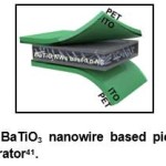
Hadimani et al. melted pure PVDF homopolymer and drawn fiber; they were polarized at 13 kV voltage at the end of the fiber drawing process. The drawn fibers were placed between two PET films coated with ITO and the voltage sensitive test was carried out in the impact tester. This device weighs 1.02 kg and is lowered on the film from a height of 5 cm. The same test was also carried out on a commercial piezoelectric PVDF filament and it was observed that the drawn PVDF fibers performed about 2 times lower (5 V / 2.2V) than the commercial PVDF filament. The main reason for the loss of performance is that PVDF used for fiber drawing is selected from a cheap raw material that is not specifically manufactured for the piezoelectric effect as it is in the commercial film. This shows that; harvesting energy from piezoelectric polymers by lowering costs is a strong candidate for renewable energy sources, despite a 50% loss.40 In another flexible nanogenerator operation,41 a two-step mechanism was used to produce BaTiO3 nanowires. PDMS film cured on a silicon plate; BaTiO3 nanoparticles coated on PDMS; A layer of PDMS is further coated on the nanowire. This dielectric layer was removed from the silicon plate and placed between two ITO coated thin and thick PET films (Figure 9).
Figure 9: BaTiO3 nanowire based piezoelectric nanogenerator.41
|
|
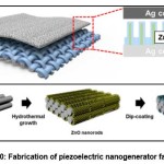
Seung et al (2015),42 piezoelectric nanogenerator fabrics were fabricated to produce wearable technology in their work (Figure 10).
Figure 10: Fabrication of piezoelectric nanogenerator fabrics.42
|
|
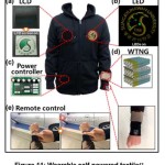
The “Sungkyunkwan University” logo was displayed using the power generated by the nanogenerator in polarized LCD manufactured from the nanogenerator fabric, and six LEDs were lit at the same time (Figures 11a-11b). A remote control used for the keyless entry system was operated using a commercial capacitor (1200 μF) charged by the nanogenerator only (Figure 11c-11e) without any assistance from an external charging source.42
Two different designs in the d31 mode have been studied by Shenck and Paradiso (2001). At first, multi-layered flexible PVDF is mounted under the shoe soles. Multi-layer PVDF film is formed as PVDF-Epoxy-Flexible plastic. In the second case, two PZT / metal unimorph components are placed underneath the ball, and this design is called bimorph. When pressure is applied and released, load accumulates along the surface of the PZT; This charge is transferred from the bimorph device via the Be / Cu electrode. These devices provide energy efficiency of 0.5% and 20% respectively.43
In another example44, PVDF was dissolved in DMF or DMAc followed by films of 20-60 μm thickness. The two surfaces of the films were covered with gold, and these layers served as electrodes. Produced film is attached to shoe soles with shaker. The shaker has strengthened the vibration that occurs during walking. A maximum voltage of 6 V was produced from 28 μm film.
Footwear applications of piezoelectric nanogenerators give high accuracy results in describing human walking cycles,45 walked gym,46 acceleration and deceleration tendencies due to high output voltages, voltage sensitivities and easy application.
Figure 11: Wearable self-powered textile.42
|
|
In a work done for industrial machines, a piezoelectric impulse excitation approach was developed. Here, a cylindrical mass is actuated by a series of piezoelectric bimorph-beam magnetic attraction.47 With the first warning, transducers start vibrating naturally frequency. Using this approach, the working frequency range can be extended while the electromechanical coupling increases significantly. The principle of current excitation is shown using an integrated circuit on the market for voltage regulation. With a 2 Hz frequency and an acceleration of 2.7 m s-2, the nanogenerator has a maximum power output of 2.1 mW. Here, the mass starts to move under the magnetic field and generates energy at the same level because it stimulates the magnets connected to the piezoelectric beams at the same level in each cycle. If the frequency of the mass increases, the energy produced will also increase. Steel was used as a mass in the study.
In another work proposed for electric generation from the knee motion, a circular design was prepared and the bimorph strata were horizontally extended to the outer edge from the centre of the field. At the edge of the outer circumference, polyimide pens were placed at regular intervals. Positioned parallel to the knee, this device caused the bimorph films to stuck and stretch and produce electrical stress when the step was taken.48 The bimorph layer is a metal film between two layers with a thickness of 125 μm. A voltage of 2.7 mV (2 Ω-300 Hz) to 24 V (1 MΩ-320 Hz) was obtained from the device at different electrical loads.
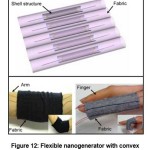
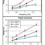
In flexible piezoelectric films, a shell layer is required to achieve high voltage output and to allow both flexing and deformation protection. Promise; a PVDF film cambered polymer film used as a piezoelectric layer may be an example of this.49 Here, the polyester film was subjected to heat treatment to make it convex, followed by a PVDF layer having copper electrodes at both ends on its inner side (Figure 12). A marked increase in performance was observed when compared to the samples made using the flattened PET film. When the output voltage is about 10 V in the flat structure and folded with the angle of 80° in the convex structure, this value increases to 60 V.
Figure 12: Flexible nanogenerator with convex shell layer.49
|
|
When the produced flexible nanogenerators are embedded in the fabrics, there is a system that transforms the mechanical energy of the joint movements into electrical energy. When the transformation of the mechanical energy in the elbow and finger joints on this system is examined, it is seen that the highest values have the highest slope values (Figure 13).
Figure 13: Stimulation of convex nanogenerator with elbow and finger movement; responses from the nanogenerator. (K: curvature degree of shell layer).49
|
|
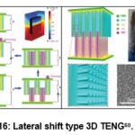
In 2012, a design has been signed for the conversion of waste mechanical energy of rotating devices for residential use of flexible nanogenerators. In the design, a rigid PZT piezoelectric beam and a flexible beam are placed perpendicular to the axis of rotation of a rotating household article. During rotation, the flexible beam physically stimulates the piezoelectric beam, causing the load carriers to polarize.50
Lee has produced a piezoelectric nanogenerator by using a ZnO film. 3 different piezoelectric layer design have been used in this work; ZnO film, ZnO/P3HT layer and ZnO/PCBM-P3HT. The resulting tests revealed a voltage of 0.05 V in the resulting ZnO nanogenerator, which increased to 0.2 V in ZnO / P3HT devices. The energy conversion efficiency increased by 28% with a potential of 0.5 V output in ZnO / P3HT-PCBM nanogenerators, increasing by 36 times.51
In another study, the electrodes were selected from conducting polymers that connecting the piezoelectric films. The fiber drawing method originally used for this work was made possible by conductive solid filled LDPE films. In this fiber drawing method, different piezoelectric layers and carbon black doped LDPE electrodes are placed on top of each other and twisted to form fiber. For piezoelectric films, BaTiO3, PZT or CNT is dispersed in the PVDF matrix. Once the overlaid films are allowed to soften at temperature, the polycarbonate is bent in one direction around an axis. The fabric woven with these fibers produced power up to about 5 V by folding and releasing movements like the photo.52
Soin et al demonstrated “3D spacer” technology based all-fibre piezoelectric fabrics as power generators and energy harvesters. The knitted single-structure piezoelectric generator consists of high β-phase (80%) piezoelectric PVDF monofilaments as the spacer yarn interconnected between silver (Ag) coated polyamide multifilament yarn layers acting as the top and bottom electrodes. The novel and unique textile structure provides an output power density in the range of 1.10–5.10 mW cm_2 at applied impact pressures in the range of 0.02–0.10 MPa, thus providing significantly higher power outputs and efficiencies over the existing 2D woven and nonwoven piezoelectric structures.53
Yu et al PVDF nanofiber-based piezoelectric nanogenerators are directly prepared via electrospinning without any post-poling treatment. The effect of the addition of multi-walled carbon nanotubes (MWCNTs) on the fibre diameter, mechanical properties, β-phase composition, surface and volume conductivities, output voltage and output power are investigated. Increased surface conductivity of the polyvinylidene fluoride (PVDF) nanofibre mats, which plays an important role in the enhancement of output power, is first found by the addition of an appropriate amount of MWCNTs. The maximum generated piezo-voltage exhibited by PVDF nanofibre mats in the presence of 5 wt% MWCNTs is as high as 6 V, while the average capacitor charging power is 81.8 nW, increases of 200% and 44.8%, respectively, compared with bare PVDF nanofibre mats.54
Hu55 has synthesized nanotubes horizontally aligned on a polyurethane substrate by thermochemical method. Then, a portion of the nanotube surface is coated with ZnO by means of an ADL reactor and filled with MWCNT by polymerizing the parylene to mechanically stabilize it. The prepared layered structure was glued with silver paste from two sides and after the electrodes were prepared, the torsion test was carried out. It was observed that the output voltage of 1.7 V was reached. In addition, measurements were taken with the same test, parallel and anti-parallel connection of two generators. Up to 2V of voltage was obtained in parallel measurements and no significant movement was observed in the anti-parallel test.
In a study of 2016, PVDF solutions (0-0.1-1.0-3.0-5.0) with different amounts of graphene in DMF were prepared. From these solutions, nanofibers produced by the electrospinning method were sandwiched between two metal electrodes and piezoelectric nanogenerators were produced. In piezoelectric measurements, the output voltage was 2 times higher than that of graphene-free device.56
Triboelectric Nanogenerators (TENGs)
The triboelectric effect is that a material becomes electrically charged after contact with a different material by friction57.TENGs are based on the principle that when two different surfaces come into contact with each other, electrons are transferred from one to another and that a surface maintains electrons more than the other while the contact is cut off. When these two surfaces are isolated, electron transfer takes place between the positive and negative poles formed. Thus, electrical stress is produced.58 TENGs are separated by four types according to contact modes:
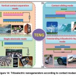
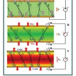
a. Vertical Contact: Electrodes are placed on one surface of the two-pole dielectric film. The physical contact between the two dielectric films creates oppositely charged surfaces. Electron flows when the plates contact, and charge accumulation when the contacts are cut (Figure 14a).
b. Lateral slip: Slip parallel to the surface when two dielectric films are in contact, creating triboelectric charges on two surfaces. Polarization in the direction of friction directs electrons in the upper and lower electrodes to flow to completely balance the charges (Figure 14b).
c. Single-Electrode: Approach or separation of TENG to the ground of dielectric filament changes local electric field distribution; so that electrons exchange between the bottom electrode and the ground to maintain the film potential change (Figure 14c).
d. Non-Connected Electrode: When a symmetric electrode pair is placed underneath a dielectric layer, a self-charged object is moved to the electrodes when moving, and the object moves away from the electrodes, creating a charge distribution in the medium(Figure 14d).57
Figure 14: Triboelectric nanogenerators according to contact modes.57
|
|
Among the factors that affect the performance of TENGs, sufficient load separation and friction area are two main factors. The load separation depends on the electronegativities of the materials used in the device. For the frictional field, developing a device from a 2D layered structure to a 3D device would be an efficient choice. In past studies, PDMS foam was produced to increase the contact surface and TENG was designed from this foam layer (Figure 15).59 In another study that used this idea, both a 3D structure and a surface were coated with nanostructures to increase the surface area of the electrodes (Figure 16).60
Figure 15: PDMS foam layered TENG.59
|
|

Figure 16: Lateral shift type 3D TENG.60
|
|
TENGs have been attracting attention among energy collectors because of advantages such as simple production, high stability, low cost. In past studies, textile applications of TENGs are always based on the contact of two threads or the cutting of contact. However, since the textile products are soft, the net contact distinctions become more difficult as the triboelectric mechanism is required. So wearable electronics are suffering from loss of comfort. Lai et al. came up with a TENG they produced from untamed yarn from above.61
Figure 17: Non-woven textile based TENG.61
|
|

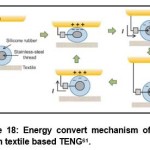
Stainless steel thread is covered with silicone rubber. This yarn was sewn on both sides of a flexible fabric in a curved manner (Figure 17). The triboelectric wire on the inner surface of the fabric acts as the second triboelectric electrode when it contacts human skin. Silicone electron transfer occurs when the skin is in contact with the silicon layer; when contact is interrupted, the negative charge on the silicon provides positive pole formation as long as it is a contact with the conductive thread (Figure 18).
Figure 18: Energy convert mechanism of non-woven textile based TENG.61
|
|
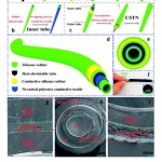
In a similar study62, a core shell coaxially triboelectric thread was produced. A heat shrinkable tube was coated by silicone rubber/conductive silicone rubber/silicone rubber. This structure is used as outer triboelectric surface. On second step a silicone rubber hollow tube which has smaller diameter than outer triboelectric layer was wrapped by Ni coated polyester fabric. This structure was used as inner triboelectric surface. Then inner tube was inserted into outer tube and two ends of triboelectric tube was coated with silicone rubber to prevent contamination. In the last step air was injected into the triboelectric core-shell structure to form a gas bag (Figure 19). Core-shell triboelectric structure was produced 380 V and 11 µA under 300 N pressure and 3 Hz frequency. A rectifier circuit was used for convert alternative current to direct current and use the electrical energy from parallel linked six core-shell structures. By this way the device could powered up 60 LEDs and an electronic watch.
Figure 19: Production processes, schematic illustrations and SEM images of core-shell triboelectric nanogenerator.62
|
|
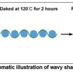
Lin et. al. have produced a sleeping sensor which is working with triboelectric effect63. Triboelectric sensor is consisting of wavy shaped PET tapes between two conductive fabric. Carbon fibres are washed by organic solvents and water. Then carbon fibres were kept on 100 °C after coating with silver nitrate and dipping edetic acid solution. Thus Ag coated conductive fibres could be produced. Conductive fibres are mounted on two fabrics with perpendicular orientation. Wavy shaped PET foils were cut 50 mm X 60 mm. Then PETs foils were kept at 120°C and wavy shape was brought with metal rods (Figure 20).
Figure 20: Schematic illustration of wavy shaped PET foil.63
|
|
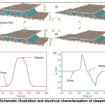
Wavy shaped PET foils were placed on intersections of conductive lines on fabrics(Fig B). Triboelectric nanogenerator based sleeping sensor was working with 0.77 V/Pa definition. The sensor is comprised 4 X 4 (16 point) intersection point with a rectangular shape. Sensor have shown enough syncronzation with external force(Figure 21).
Figure 21: Schematic illustration and electrical characterization of sleeping sensor.63
|
|
Conjugated polymers are preferred as electrode in nanogenerators because of their conductive disposition. Electrode designs that cannot be realized with metals can be realized with conductive polymers due to their polymeric character.64
Wang et al. have offered an innovative device design to nanogenerator-supercapacitor systems. A triboelectric electrode is additionally coated onto top electrode and electrical contact is provided with polyimide based films. In this study, nanogenerator produced 28 V potential at 10Hz; besides supercapacitor stored this potential.65
Cui has electro-polymerized pyrrole on an anodic aluminium oxide porous pattern which was used for production of polypyrrole nano-forest. Polypyrrole is preferred as electrode due to its fast redox performance, flexibility and low cost. Triboelectric electrode of the device consists of respectively Ag/PE/PVDF film. Triboelectrode is fixed on polypyrrole electrode and and four acrylic sheets is used as spacer. While PVDF layer charges under stable condition, on the other hands, decharge is observed when the PVDF layer touches to polypyrrole nanowires with wind power.66
According to a study in 2015, textile product is prepared by using both supercapacitors and TENGs to produce a wearable electronics. TENG fabric is woven with Ni coated polyester yarn is used as weft, while parylene-Ni coated polyester yarn is used as warp. TENG device fabrication is completed by combining TENG fabric and a cotton fabric. When the cotton layer touch the TENG fabric charge is observed on both weft and warp yarn.67
Huang et al. have developed a nanogenerator shoe sole. In this study, PVDF nanofiber layer is used as triboelectric electrode thanks to high electronegativity difference between side groups of PVDF. Counter triboelectric electrode was copper and nickel coated polyethylene terephthalate fabrics. TENG shoe sole could achieved to produce electrical potential till 210 V.68
Pyroelectric Nanogenerators
Pyroelectric property is at least one of the known properties of the solids is defined as the temperature dependence of polarization in certain anisotropic layer. Pyroelectric materials, net dipole moment and the temperature change (or bound charge) they introduce the changes. Pyroelectric nanogenerator are widely used in petroleum refining, steelmaking, glassmaking, such as waste heat of industrial processes or natural geothermal heat obtained from volcanic heat using the solar heat sources such as hot water / cold water charging by utilizing the difference / discharge occur is provided (Figure 22). Made of a pyroelectric nanogenerator studies69 the two faces of the copper-plated of a PVDF film (electrode), a contact wire from the electrodes for measuring the electricity generated is removed, then the entire device is coated with PVC. The temperature difference between the hot and cold water is 80 °C 192 V voltage and 12 mA / cm2 current density reached.
Figure 22: Pyroelectric effect.69
|
|
Conclusions
Nanogenerators have emerged to target the recovery of energy used mechanically, biologically or radially inefficiently; in the case of macro sizes, the possibility of producing these quantities of energy producing devices, in small quantities with simple devices that require energy to produce their own energy has produced systems. Electronically, electrostatically, or piezo-electrically, these devices are particularly well suited to revolutionize device design as well as electric energy production, particularly in factories, vehicles, and in areas where mechanical energy is present in high amounts, such as human body, in small quantities or high frequency. The fact that these devices come to the flexible form promises higher efficiency by capturing more mechanical force on the axle compared to the rigid construction when the energy is harvested. In addition, these devices, which are more sensitive to the force axis, may even have a sensor system on their own. Flexible nanogenerators can be predicted to play a large role, especially in biomedical developments. For example, they can be used as breathe sensors39, joint motion sensors48,49 etc.
With the growing development of wearable and implantable devices, nanogenerators (NGs) have been paid attention in recent years due to their high conversion efficiency and low-cost with organic nanomaterials13,15,21. The powers of micro/nano scale devices or systems supplied by traditional batteries have some problems such as miniaturization, compatibility and long lifetime14,60. Thus harvesting the energy from environments by NGs can be a potential and effective alternative to meet such requirements. The traditional mechanisms of nanogenerators have been reviewed9,32-41, including electrostatic3,46,62,63,66,67, piezoelectric4,10 and electromagnetic19,50 methods. However, those devices usually cannot satisfy the need of power supply for electronic devices due to their complex fabrication processes, low output power and biocompatibility for medical applications. Moreover, most of devices work under single mechanism and their output performance is actually limited in service. Advances in nanotechnology, novel and viable device designs as well as applications of new nanomaterials will enhance better results in flexible nanogenerators.
Acknowledgment
This research was supported by Bursa Technical University, Scientific Research Projects (BAP), Project No:172L01.
Conflict of interest
“The author(s) declare(s) that there is no conflict of interests regarding the publication of this article”.
Funding Source
“The author(s) declare(s) that the funding is done by author only.
References
- Wang X., Yang B., Liu J., Zhu Y., Yang C & He Q. A flexible triboelectric-piezoelectric hybrid nanogenerator based on P(VDF-TrFE) nanofibers and PDMS/ MWCNT for wearable devices. Scientific Reports. 2016;6:1-10.
CrossRef - Wang Z. L., Song J. Piezoelectric nanogenerators based on zinc oxide nanowire arrays. Science. 2006;312:242-245.
CrossRef - Gu L., Cui N., Cheng L., Xu Q., Bai S., Yuan M.,Wu W., Liu J., Zhao Y., Ma F.,Qin Y., Wang Z. L. Flexible Fiber Nanogenerator with 209 V Output Voltage Directly Powers a Light-Emitting Diode. Nano Letters. 2013;13:91-94.
CrossRef - Sankar R. G., Sharma S. K.,Abinnas N., Durgadevi E., Raji P.,Ponnusamy S., Muthamizchelvan C. Y., Hayakawa D. Y. K. Fabrication of the flexible nanogenerator from BTO nanopowders on graphene coated PMMA substrates by sol-gel method. Materials Chemistry and Physics. 2017;192:274-281.
CrossRef - Park K. I., Jeong C. K., Kim N. K., Lee K. J. Stretchable piezoelectric nanocomposite generator. Nano Convergence. 2016;3:
- Han C., Zhang C., Tang W., Li X., Wang Z. L. High power triboelectric nanogenerator based on printed circuit board (PCB) technology. Nano Research. 2014.
- K.I. Park, J.H. Son, G.T. Hwang, C.K. Jeong, J. Ryu, M. Koo, I. Choi, S.H. Lee, M. Byun, Z.L. Wang, K.J. Lee. Highly-Effi cient, Flexible Piezoelectric PZT Thin Film Nanogenerator on Plastic Substrates. Advanced Materials. 2014;26:2514-2520.
CrossRef - Wang Z. L. Nanopiezotronics. Advanced Materials. 2007;19:889-892.
CrossRef - Fukada E. Piezoelectricity in polymers and biological materials. Ultrasonics. 1968.
- Fukada E. Piezoelectric properties of organic polymers. Annals New York Academy of Sciences: Part I: Physical and Chemical Studies. 1974.
- Jeon Y. B., Sood R., Jeong J., Kim S. G. MEMS power generator with transverse mode thin film PZT. Sensors and Actuators. 2005.
CrossRef - Wang L.,Yuan F. G. Vibration energy harvesting by magnetostrictive material. Smart Materials and Structures. 2008;17:45009-45023.
CrossRef - Choi W. J., Jeon Y., Sood R., Kim S. G. Energy harvesting MEMS device based on thin film piezoelectric cantilevers. Journal of Electroceramics. 2006;17:543-548.
CrossRef - Erturk A and Inman D. J. Piezoelectric Energy Harvesting. John Wiley and Sons, West Sussex, UK. 2011:3-4.
CrossRef - Das J., Li M., Kalarickal S. S.,Altmannshofer S., Buchanan K. S., Li F., Viehland D. Control of magnetic and electric responses with electric and magnetic fields in magnetic heterostructures. Applied Physics Letters. 2010;96:222508.
CrossRef - Ling B. K., Li T., Hng H. H., Boey F., Zhang T and Li S. Waste Energy Harvesting: Mechanical and Thermal Energies. Springer. 2014:21.
- Tan Y. K. Sustainable Energy Harvesting Technologies–Past, Present and Future. InTech, Rijeka. 2011;28-29.
CrossRef - Ottman G. K., Lesiutre G. A. Optimized Piezoelectric Energy Harvesting Circuit Using Step-Down Converter in Discontinuous Conduction Mode. Transactions on Power Electronics. 2003;18.
- Guyomar D., Badel A., Lefeuvre E. C. Richard. Toward Energy harvesting Using Active Materials and Conversion Improvement by Nonlinear Processing. Ultrasonics, Ferroelectrics and Frequency Control. 2005;52:584-595.
CrossRef - Khan A., Edberg J., Nur O., Willander M. A novel investigation on carbon nanotube/ZnO, Ag/ZnO and Ag/carbon nanotube/ZnO nanowires junctions for harvesting piezoelectric potential on textile. Journal Of Applied Physics. 2014;116.
- S.K. Amin, M. Hassan, H. Abdallah. An overview of production and development of ceramic membranes. International Journal of Applied Engineering Research. 2016;11:7708-7721.
Crossref - Nakayama K.S., Yokoyama Y., Wada T., Chen N., Inoue A. Formation of Metallic Glass Nanowires by Gas Atomization. Nano Letters. 2012;12:2404-2407.
CrossRef - L.Q. Cheng, J.F. Li, A review on one dimensional perovskite nanocrystals for piezoelectric applications. Journal of Materiomics. 2016;2:25-36.
CrossRef - Li X., Sun M., Wei X.,Shan C.,Chen Q. 1D Piezoelectric Material Based Nanogenerators: Methods, Materials and Property Optimization. Nanomaterials. 2018;8:188.
CrossRef - Cheng L .Q., Wang K., Li J. F. Synthesis of highly piezoelectric lead-free (K,Na)NbO3 one-dimensional perovskite nanostructures. Chemical Communications. 2013;49:4003-4005.
CrossRef - Ling B. K., Li T., Hng H. H., Boey F., Zhang T and Li S. Waste Energy Harvesting: Mechanical and Thermal Energies. 24, Springer. 2014;254-255.
- Chang C.,Tran V. H., Wang J. B., Fuh Y. K., Lin L.W. Direct-write piezoelectric polymeric nanogenerator with high energy conversion efficiency. Nano Letters. 2010;10:726.
CrossRef - Pu J., Yan X. J., Jiang Y. D., Chang C., Lin L.W. Piezoelectric actuation of direct-write electrospun fibers. Sensors Actuators A. 2010;164:131.
CrossRef - Dhakras D., Borkar V., Ogale S., Jog J. Enhanced piezoresponse of electrospun PVDF mats with a touch of nickel chloride hexahydrate salt. Nanoscale. 2012;4:752.
CrossRef - Fang J., Wang X. G., Lin T. Electrical power generator from randomly oriented electrospun poly(vinylidene fluoride) nanofiber membranes. Journal of Materials Chemistry. 2011;21:11088.
CrossRef - Wang Y. R., Zheng J. M., Ren G. Y., Zhang P. H., Xu C. C. A flexible piezoelectric force sensor based on PVDF fabrics. Smart Mater. Struct. 2011;20:045009.
CrossRef - Hu J. M., Moigno D., Kiefer W., Ma J. S., Chen Q. Q., Wang C. Q., Feng H. T., Shen J. K.,Niu F., Gu Y. H.. Fourier-transform Raman and infrared spectroscopic analysis of novel biliverdin compounds. Spectrochim. Acta. A. 2000;56:2365.
CrossRef - Stidham H. D.,Duffy D. J., Hsu S. L., Guirgis G. A., Durig J. R. Raman and infrared spectra, conformational stability, ab initio calculations and assignment of fundamentals for 1-bromo-3-fluoropropane. Spectrochim. Acta. A. 2001;57:1567.
CrossRef - Lin L., Hu Y., Xu C., Zhang Y., Zhang R., Wen X., Wang Z. L., Transparent flexible nanogenerators as self-powered sensor for transportation monitoring. Nano Energy. 2013;2:75-81.
CrossRef - Ding R., Zhang X., Chen G., Wang H., Kishor R., Xiao J., Gao F., Zeng K., Chen X.,Sun X. W., Zheng Y. High-performance piezoelectric nanogenerators composed of formamidinium lead halide perovskite nanoparticles and poly(vinylidene fluoride). Nano Energy. 2017;37:126-135.
CrossRef - Jung J. H., Lee M.,Hong J. I., Ding Y., Chen C. Y., Chou L. J., Wang Z. L. Lead-Free NaNbO3 Nanowires for a High Output Piezoelectric Nanogenerator. Acs Nano. 2011;5:10041-10046.
CrossRef - Lee K. Y., Kim D., Lee J. H., Kim T. Y., Gupta M. K., Kim S. W. Unidirectional High-Power Generation via Stress-Induced Dipole Alignment from ZnSnO3 Nanocubes/Polymer Hybrid Piezoelectric Nanogenerator. Advanced Functional Materials. 2014;24:37-43.
CrossRef - Fuh Y. K.,Wang B. S. . Near field sequentially electrospun three-dimensional piezoelectric fibers arrays for self-powered sensors of human gesture recognition. Nano Energy. 2016;30:677-683.
CrossRef - Liu Z., Zhang S.Jin Y. M.,Ouyang H., Zou Y., Wang X. X., Xie L. X., Li Z. Flexible Piezoelectric nanogenerator for Wearable Self-Powered Respiration Active Sensor and Healthcare Monitoring. Semiconductor Science and Technology. 2017;32.
CrossRef - Hadimani R. L., Bayramol D.V.,Sion N., Qian S. S., Siores E. Continuous production of PVDF fibre for e-textile applications. Smart Materials and structures. 2013;22.
- Park K. I., Bae S. B., Yang S. H., Lee H. I., Lee K., Lee S. J. Lead-free BaTiO3 nanowires-based flexible nanocomposite generator. Nanoscale. 2014.
- Seung W., Gupta M. K., Lee K. Y., Shin K. S., Lee J. H., Kim T. Y., Kim S., Lin J., Kim J. H.,Kim S.W. Nanopatterned Textile-Based Wearable Triboelectric Nanogenerator. ACS Nano. 2015.
- N.S. Shenck, J.A. Paradiso. Energy Scavenging With Shoe-Mounted Piezolectrics. IEEE Micro. 2001;21:30-42.
CrossRef - Fourier D. Shoe-Mounted PVDF Piezoelectric Transducer for Energy Harvesting. Materials Systems and Structures. 2010.
- Ledoux W. R., Hillstrom H. J. Acceleration of the calcaneus at heel strike in neutrally aligned and pes planus feet. Clinical Biomechanics. 2001;16:608-613.
CrossRef - Giddings V. L.,Beaupre G. S., Whalen R. T., Carter D. R. Calcaneal loading during walking and running. Medicine & Science In Sports & Exercise. 2000.
- Pillatsch P., Yeatman E. M., Holmes A. S. A scalable piezoelectric impulse-excited energy harvester for human body excitation. Smart Materials and Structures. 2012;21:115018-115027.
CrossRef - Pozzi M.,Zhu M. Plucked piezoelectric bimorphs for knee-joint energy harvesting: modeling and experimental validation. Smart Materials and Structures. 2011;20:55007-55017.
CrossRef - Yang B.,Yun K. S. Piezoelectric shell structures as wearable energy harvesters for effective power generation at low-frequency movement. Sensors and Actuators A. 2012;188:427-433.
CrossRef - Gu L., Livermore C. Compact passively self-tuning energy harvesting for rotating applications. Smart Materials and Structures. 2012;21.
CrossRef - Lee K. Y., Kumar B., Seo J. S., Kim K. H., Sohn J. I., Cha S. N., Choi D., Wang Z. L., Kim S. W. P-Type Polymer-Hybridized High Performance Piezoelectric Nanogenerators. Nano Letters. 2012;12:1959-1964.
CrossRef - Lu X., Qu H., Skorobogatiy M. Piezoelectric Micro-and Nanostructured Fibers Fabricated from Thermoplastic Nanocomposites Using a Fiber Drawing Technique: Comparative Study and Potential Applications. ACS Nano. 2017.
- Soin N., Shah T. H., Anand S. C., Geng J., Pornwannachai W., Mandal P., Reid D., Sharma S., Hadimani R. L.,Vatansever D. B., Sioresa E. Novel “3-D spacer” all fibre piezoelectric textiles for energy harvesting applications. Energy and Environmental Science. 2014;5.
- Yu H., Huang T., Lu M., Mao M.,Zhang Q., Wang H. Enhanced power output of an electrospun PVDF/MWCNTs-based nanogenerator by tuning its conductivity. Nanotechnology. 2013;24:405401.
CrossRef - Hu C. J., Lin Y. H.,Tang C. W., Tsai M. Y., Hsu W. K., Kuo H. F. ZnO Coated Carbon Nanotubes: Flexible Piezoelectric Generators. Advanced Materials. 2011;23:2941-2945.
CrossRef - Abdolhasani M. M., Shirvanimoghaddam K., Naebe M. PVDF/Graphene Composite Nanofibers with enhanced piezoelectric performance for development of robust nanogenerators. Composites Science and Technology. 2016.
- Wang Z. L. Triboelectric nanogenerators as new energy technology and self-powered sensors–Principles, problems and perspectives. Faraday Discussions. 2014;176:447-458.
- Kim J., Lee J. H.,Lee J., Yamauchi Y., Choi C. H., Kim J. H. Hybrid energy devices combining nanogenerators and energy storage systems for self-charging capability. APL Materials. 2017;5.
- Lee K. Y., Chun J., Lee J. H., Kim K. N., Kang N. R., Kim J. Y., Kim M. H., Shin K. S.,Gupta M. K., Baik J. M.,Kim S. W. Hydrophobic Sponge Structure-Based Triboelectric Nanogenerator. Advanced Materials. 2014;26:5037-5042.
- Du W.,Han X., Lin L., Chen M., Li X., Pan C. Z. L. Wang Z. L. A Three Dimensional Multi-Layered Sliding Triboelectric Nanogenerator. Advanced Energy Materials. 2014;4.
- Lai Y. C., Deng J., Zhang S. L., Niu S., Guo H., Wang Z. L. Single-Thread-Based Wearable and Highly Stretchable Triboelectric Nanogenerators and Their Applications in Cloth-Based Self-Powered
- Tian Z., He J., Chen X., Wen T., Zhai C.,Zhang Z., Cho J., Chou X., Xue C. Core–shell coaxially structured triboelectric nanogenerator for energy harvesting and motion sensing. RSC Advances. 2018;8:2950-2957.
CrossRef - Lin Z.,Yang J., Li X., Wu Y., Wei W., Liu J., Chen J., Yang J. Large‐Scale and Washable Smart Textiles Based on Triboelectric Nanogenerator Arrays for Self‐Powered Sleeping Monitoring. Advanced Functional Materials. 2018;28:1.
CrossRef - Ko E. J., Lee E. J., Choi M. H., Sung T. H., Moon D. K. PVDF based flexible piezoelectric nanogenerators using conjugated polymer: PCBM blend systems. Sensors and Actuators A: Physical. 2017;259:112-120.
CrossRef - Wang J.,Wen Z., Zi Y., Zhou P., Lin J., Guo H., Xu Y., Wang Z. L. All-Plastic-Materials Based Self Charging Power System Composed of Triboelectric Nanogenerators and Supercapacitors. Advanced Materials. 2015;26:1070-1076.
- Cui S., Zheng Y., Liang J., Wang D. Conducting polymer PPy nanowire-based triboelectric nanogenerator and its application for self-powered electrochemical cathodic protection. Chemical Science. 2016;7:6477-6483.
CrossRef - Pu X., Li L., Liu M., Jiang C., Du C., Zhao Z., Hu W., Wang Z. L. Wearable Self-Charging Power Textile Based on Flexible Yarn Supercapacitors and Fabric Nanogenerators. Advanced Materials. 2015;28:98-105.
CrossRef - Huang T., Wang C., Yu H.,Wang H., Zhang Q., Zhu M. Human walking-driven wearable all-fiber triboelectric nanogenerator containing electrospun polyvinylidenefluoride piezoelectric nanofibers. Nano Energy. 2015;14:226-235.
CrossRef - Leng Q., Chen L., Guo H., Liu J., Hu C., Xi Y. Harvesting heat energy from hot/cold water with a pyroelectric generator. Journal of Materials Chemistry. 2014;2:11940-11947.
CrossRef
Accepted on: 25-07-2018
Second Review by: Dr. S.Ravichandran
Final Approval by: Dr. Jit Satyabrata


![]()
![]()
![]()