design and Analysis of a Heat Exchanger Network
Department of Mechanical Engineering, Hindustan University, Chennai - 603 103 (India)
DOI : http://dx.doi.org/10.13005/msri/090111
Download this article as:
![]()
This paper deals with the detailed design and analysis of a heat exchanger network. Due to the importance of heat exchanger in chemical and petrochemical industries, analysis of heat exchanger network and heat transfer calculation is preceded. The research aimed at calculating
the hot fluid outlet temperature, cold fluid outlet temperature, heat transfer rate and effectiveness at varying hot and cold fluid inlet temperatures using, log mean temperature difference (LMTD) and effectiveness-number of transfer units (ε-NTU) method. The obtained result illustrates how heat transfer rate and effectiveness increases or decreases at varying hot and cold fluid inlet temperatures. The result obtained from both LMTD and å-NTU method gives statistically significant values. The objective of this paper is to find out the optimal temperature at which heat transfer rate and effectiveness are maximum.
Heat exchanger network; Shell and tube heat exchanger; Heat exchanger design and analysis; Heat transfer rate and effectiveness
The LMTD method can be readily used when the inlet and outlet temperatures of both the hot and cold fluids are known. When the outlet temperatures are not known, the LMTD can only be used in an iterative scheme. In this case the effectiveness-NTU method can be used to simplify the analysis. The choice of heat exchanger type directly affects the process performance and also influences plant size, plant layout, length of pipe runs and the strength and size of supporting structures.
Heat exchangers may be classified according to their flow arrangement. Counter current heat exchangers are most efficient because they allow the highest log mean temperature difference between the hot and cold streams. In a cross-flow heat exchanger, the fluids travel roughly perpendicular to one another through the exchanger. For efficiency, heat exchangers are designed to maximize the surface area of the wall between the two fluids, while minimizing resistance to fluid flow through the exchanger. The exchanger’s performance can also be affected by the addition of fins or corrugations in one or both directions, which increase surface area and may channel fluid flow or induce turbulence.
Fouling occurs when a fluid goes through the heat exchanger, and the impurities in the fluid precipitate onto the surface of the tubes. Precipitation of these impurities can be caused by: Frequent use of the heat exchanger, not cleaning the heat exchanger regularly, reducing the velocity of the fluids moving through the heat exchanger and over-sizing of the heat exchanger. Effects of fouling are more abundant in the cold tubes of the heat exchanger than in the hot tubes.This is because impurities are less likely to be dissolved in a cold fluid. This is because, for most substances, solubility increases as temperature increases. A notable exception is hard water where the opposite is true. Fouling reduces the cross sectional area for heat to be transferred and causes an increase in the resistance to heat transfer across the heat exchanger. The most commonly used type of heat exchanger is the shell-and tube heat exchanger, the optimal design of which is the main objective of this study.
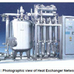
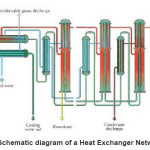
Shell-and-tube heat exchangers are probably the most common type of heat exchangers applicable for a wide range of operating temperatures and pressures.They have larger ratios of heat transfer surface to volume than double-pipe heat exchangers, and they are easy to manufacture in a large variety of sizes and flow configurations. Their construction facilitates disassembly for periodic maintenance and cleaning. Shell-and-tube heat exchangers find widespread in chemical process industries, in conventional and nuclear power stations, steam generators, etc. This widespread use can be justified by its versatility, robustness and reliability. Despite the technological advances of other exchanger types (e.g., plate-and- frame, spiral, lamella, etc.), shell-and-tube heat exchangers will maintain a central position in industrial activities in the next years. Due to the important role of shell-and-tube heat exchangers, a considerable number of papers have been devoted to the design optimization problem. The design of a heat exchanger involves the selection/ sizing of its main mechanical components to fulfil a desired service. Fig. 1 and 2 shows the photographic view of Heat exchanger Network and the schematic diagram of a Heat Exchanger Network respectively.
Design Parameters
Material Type = 304 SS
Composition = 18% Cr, 8% Ni
Metal Thermal = 16.3
Conductivity (k) W/m K
Tube O.D = 12mm = .012 m
Length of tube = 1.85 m
Cold fluid = Water
Hot fluid = Steam
Other Properties
Cold Fluid Properties
Properties Of Water At 30 O C:
Kinematic viscosity(n) = .8315×10-6 m2/s
Thermal Conductivity(k) = .6129 W/mK
Specific heat(Cp) = 4178 J/kgK
Prandtl No(Pr) = 5.68
Methodology
The LMTD and effectiveness-NTU method have been used to find out the outlet temperatures of hot and cold fluid, heat transfer rate and effectiveness at varying hot and cold fluid inlet temperatures.
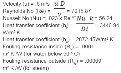
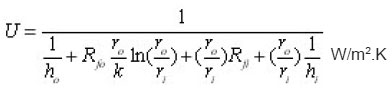
Overall heat transfer coefficient
LMTD Method
Equation for finding out hot fluid outlet temperature
Equation for finding out cold fluid outlet temperature
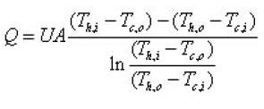
Equation for finding out Heat transfer rate
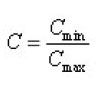
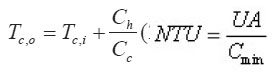
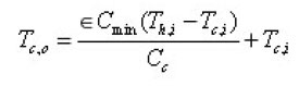
Effectiveness-NTU Method
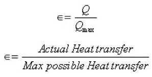
Equation for finding out NTU
Equation for finding out cold fluid outlet temperature
Equation for finding out Heat transfer rate:
![]()
Equation for finding out hot fluid outlet temperature
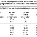
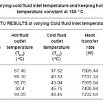
Table 1: Varying hot fluid inlet temperature and keeping cold fluid inlet temperature constant at 30 o C
 Click on image to enlarge |
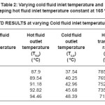
Table 2: Varying cold fluid inlet temperature and keeping hot fluid inlet temperature constant at 165 o C
 Click on image to enlarge |
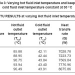
Table 3: Varying hot fluid inlet temperature and keeping cold fluid inlet temperature constant at 30 o C
 Click on image to enlarge |
Table 4: Varying cold fluid inlet temperature and keeping hot fluid inlet temperature constant at 165 o C.
 Click on image to enlarge |
Figure 1: Photographic view of Heat Exchanger Network
 Click on image to enlarge |
Figure 2: Schematic diagram of a Heat Exchanger Network.
 Click on image to enlarge |
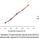
Figure 3: Variation in heat transfer rate by both LMTD and NTU method with respect to hot fluid inlet temperature
 Click on image to enlarge |
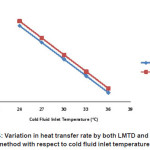
Figure 4: Variation in heat transfer rate by both LMTD and NTU method with respect to cold fluid inlet temperature
 Click on image to enlarge |
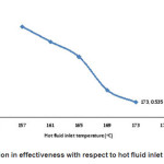
Figure 5: Variation in effectiveness with respect to hot fluid inlet temperature
 Click on image to enlarge |
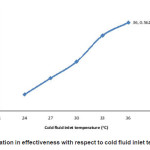
Figure 6: Variation in effectiveness with respect to cold fluid inlet temperature
 Click on image to enlarge |
Results And Discussion
|
A |
= |
Area (m²) |
Re = |
Reynolds number |
|
U |
= |
overall heat transfer |
|
(dimensionless) |
|
|
|
coefficient (W/m² K) |
Nu = |
nusselt number |
|
Q |
= |
heat transfer rate (W) |
|
(dimensionless) |
|
k |
= |
thermal conductivity (W/m K) |
TEMA = |
tubular exchanger |
|
h |
= |
convective heat transfer |
|
manufacturer association |
|
|
|
coefficient (W/m² K) |
SS = |
stainless steel |
|
C |
= |
heat capacity rate (W/K) |
Cr = |
chromium |
|
Rf |
= |
fouling resistance (m² K/W) |
Ni = |
nickel |
|
r cp |
= = |
radius (m) specific heat (J/kg K) |
Greek Symbols n = |
kinematic viscosity (m2/s) |
|
u T |
= = |
velocity (m/s) temperature (°C) |
e = Subscripts |
effectiveness |
|
LMTD |
= |
log mean temperature |
o = |
outer, outlet |
|
|
|
difference (°C) |
i = |
inner, inlet |
|
NTU |
= |
number of transfers units |
c = |
cold |
|
Δ T |
= |
temperature difference (°C) |
h = |
hot |
|
O.D |
= |
outer diameter (m) |
min = |
minimum value |
|
Pr |
= |
prandtl number |
max = |
maximum value |
|
|
|
(dimensionless) |
|
|
References
- M. Thirumarimurugan et al, Performance Analysis of Shell and Tube Heat Exchanger Using Miscible System, American Journal of Applied Sciences., 5(5): 548-552 (2008).
CrossRef - A. R. Moghadarsi et al, An Expert Model for The Shell and Tube Heat Exchangers Analysis by Artificial Neural Networks, ARPN Journal of Engineering and Applied Sciences, 6(9): (2011).
- M. M. El-Fawal et al, Modelling of Economical Design of Shell and Tube Heat Exchanger Using Specified Pressure Drop, Journal of American Sciences, 7(12): (2011).
- Andre L. H. Costa and Eduardo M. Queiroz, Design Optimization of Shell and Tube Heat Exchangers, Applied Thermal Engineering; 28: 1798-1805 (2008).
CrossRef - Ramesh K. Shah and Dusan P. Sekulic, Fundamentals of Heat Exchanger Design, John Wiley & Sons, Inc, New Jersey, 1: (2003).
- R.C. Sachdeva, Fundamentals of Engineering Heat and Mass transfer, New Age International Publication, New Delhi, (2008).
Accepted on: 30 April 2012


![]()
![]()
![]()
![]()