Satadru Kashyap*
Department of Mechanical Engineering, Tezpur University, Napaam, Sonitpur, Assam - 784 028, India.
Article Publishing History
Article Received on : 25 May 2013
Article Accepted on : 11 Jun 2013
Article Published :
Plagiarism Check: Yes
Article Metrics
ABSTRACT:
One of the most common therapeutic surface reactive bioresorbable implant material used nowadays is bioactive glass 45S5. However, being amorphous in nature, its usage in load bearing applications is ineffective due to its poor mechanical properties. A novel idea of toughening bioactive glass 45S5 would be to produce it as a glass ceramic with an optimum dispersion of a crystalline phase in the amorphous matrix so that crack deflection at and around crystals occur which would toughen bioactive glass ceramic by increasing the crack length. Partially crystallized bioactive glass therefore is a prime contender in the fabrication of a glass ceramic with improved fracture resistance. However, during crystallization it was observed that flowery patterns were produced inside the samples which upon analysis revealed to be inter-linked voids formed at the grain boundaries. These voids were formed as a result of shrinkage upon crystallization and may play influential part in the crack propagation behaviour in crystallized bioactive glass.
KEYWORDS:
Crystallization; Bioactive glass; inter-linked voids; toughening
Copy the following to cite this article:
Kashyap S. Formation of Inter-linked voids in Bioactive Glass 45S5 upon Crystallization. Mat.Sci.Res.India;10(1)
|
Introduction
Any novel material designed and fabricated to be used as a therapeutic bioimplant in order to replace damaged or diseased tissues or bones must fulfil certain criteria related to implant-tissue interaction in a living body. The necessary criteria for a successful bioimplant material must be high osteoconductivity, ability to promote regeneration of new tissue, compatibility with the host body, good biodegradability or bioresorbability, effective commercial sustainability and good mechanical properties.1-3
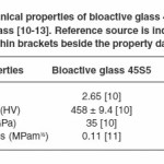
Since its inception in the late 1960s, one of the most frequently used bioactive glass is Bioglass® 45S5-a surface reactive, bioresorbable, osteoconductive glass; which has been tried and tested over the years in its usage as a structural material for biomedical implants such as repair of orthopaedic cavitary (hip) defects, cochlear implants, spinal surgery, replacement of periodontal defects and reconstruction of maxillo-facial defects.4 In spite of fulfilling all other criteria, Bioglass® 45S5 has poor mechanical properties on account of its amorphous structure which restricts its effective usage in biomedical applications as a successful implant material.5-8 Application of fundamental knowledge in developing assays for bioactive glass fabrication and characterization requires to be formulated in order to channel this gap towards an improved product with better mechanical properties. Resorbable implant materials endure some form of stress during manufacture or whilst in service. In the past, metallic alloys and ceramic composites have been used but they have issues such as toxicity and stress shielding (elastic modulus mismatch).9 A huge hindrance in expanding the application of bioactive glasses as implant materials has been their mechanical properties which are below par in terms of fracture toughness, strength, and impact resistance; thus rendering them unsuitable for life long service.10 Table 1 provides comparative mechanical properties of bioactive glass 45S5 and soda lime glass which illustrates the fragility of bioactive glass 45S5 making it inappropriate implant material in loading bearing conditions.11-14
Various techniques have been put forward to toughen bioactive glass ceramics by introducing composites in the form of particles,15-20 particle composites,21 glass ceramic composites22 and coatings.23-25 Earlier, “Glass ceramics” were developed by special heat treatment of particular glass compositions to present a uniform fine dispersion of crystals in glassy phase matrix, which gave them a cutting edge over the conventional “glass” in terms of properties such as higher strength and impact resistance, low coefficient of thermal expansion, low dielectric loss and a range of optical properties from clear to opaque or white.26-27
Hence, another thought of improving the stress carrying capability in bioactive glass ceramics would be phase transformation of amorphous structure into partially crystalline bioactive glass such that instead of straight crack propagation (usually observed in amorphous glass structure); the crystalline phases distributed in an amorphous matrix will actually deflect the crack path around them thereby increasing the crack path. This will lead to an increase in the fracture toughness. Chen et al. revealed the ability of mechanically competent crystalline sintered bioactive glass 45S5 powder to form biodegradable and bioactive calcium phosphate upon immersion in simulated body fluid28 while Kashyap et al.,29 deduced the formation of a biomineralized layer on partially crystallized bioactive glass 45S5 upon immersion in phosphate buffer solution. Evidently with the proof that crystalline bioactive glass 45S5 does not totally compromise the inherent bioactivity of the resorbable implant material, it is intended to increase the resistive capability of bioactive 45S5 glass ceramic to crack propagation by inducing crystallinity in them.
Kashyap et al.29 previously studied the crystallization kinetics of bioactive glass 45S5 by heat treating them at 680°C for various time periods (0 to 60 minutes) so as to obtain a gradual transition from amorphous to a fully crystalline structure. It was observed that along with ‘devitrification’ occurring due to crystallization, certain flowery patterns were also produced inside the samples. Moreover, Kashyap30 also reported an increase in the thermal shock and fracture resistance in partially crystallized bioactive glass 45S5 as compared to its amorphous counterpart. A bioactive glass sample heated to 680°C for 30 min (~ 68% crystallinity) generated only cracks in it upon quenching in water from that temperature while the amorphous sample shattered to pieces upon quenching from 680°C. SEM analysis of fracture surfaces in a partially crystallized sample revealed that although the sample fractured along the cracked planes, each cracked plane was blanketed with numerous small cleavage planes (mist). The numerous small cleavage planes seemed to change direction after every 30-40 microns. This suggested higher fracture resistance in partially crystalline sample as more energy was consumed for crack propagation when compared with an amorphous sample with an almost flat fracture surface showing no hindrance in crack propagation.30
Materials And Methods
Sample
Material
As cast Bioactive Glass 45S5
Chemical composition
SiO2 45 wt %, Na2O 24.5 wt %, CaO 24.5 wt % and P2O5 6 wt %.
Provider
Mo-Sci Health Care, L.L.C (Rolla, MO, USA)
Sample Morphology
Cast, annealed and amorphous 12 mm diameter cylindrical rods
Sample Preparation
Cylindrical rods of bioactive glass 45S5 were sectioned into 3mm thick discs using a slow speed saw fitted with a diamond wafering blade using isopropyl alcohol as the lubricant/coolant. The disc samples were ground, polished and ultra-sonically cleaned in an acetone bath followed by an isopropyl alcohol bath for 30 min each, before drying under compressed air.
Heat Treatment and Etching
Earlier, Bretcanu et al.,31 found that the bioactive glass 45S5 crystallizes between 600°C and 750°C while a previous study by Lefebvre et al.32 showed structural changes and alterations occurring in bioactive glass 45S5 just after its glass transition temperature of 550°C. As such, the bioactive glass samples were annealed at a temperature of 460°C for 8 hours to relieve any residual stresses present in them – well below the temperature at which the phase transformation begins. Partially and fully crystallized samples were produced by heat treating the amorphous samples at 680ºC for 30 minutes and 60 minutes respectively.29 The polished crystallized samples were etched with 0.05% HF solution for 4s for optical microscopy and SEM analysis.
Characterization
Imaging
Macrographs of amorphous and crystallized bioactive glass samples were taken with a Nikon Coolpix L100 digital camera. Optical micrographs were taken on a Nikon Epiphot 300 optical microscope fitted with a Nikon D300 DSLR camera.
For characterization, a partially crystallized sample heat-treated at 680°C for 30 minutes which had a ~ 68% crystalline phase containing almost equal amount of crystalline and amorphous regions and fully crystallized sample were chosen.29 The amorphous and crystallized bioactive glass samples were gold sputter coated prior to obtaining secondary electron micrographs using a Zeiss EVO Scanning electron microscope with a LaB6 crystal source.
Microindentation
Microindentations were made on polished amorphous and unetched fully crystalline sample (crystallized at 680ºC for 60 min) bioactive glass samples using a diamond Vickers indenter (Mitutoyo MVK-H1). Indents were made at a load of 300gf corresponding to a force of 2.943N on each sample surface and optical micrographs of the indents along with their crack paths were recorded.
Testing of Samples
Dye penetrant test
A partially crystallized bioactive glass 45S5 sample was sectioned along the cross section and subsequently polished. A black dye was spread over the polished cross sectional surface of the sample. Following that, the sample was placed on a vacuum plate and covered by an inverted vacuum jar. A gasket sealed the gap between the lip of the jar and the vacuum plate. The whole system inside the jar was brought to a vacuum by using a mechanical pump (Fisher Technical Company, LAV-3). Vacuum was maintained for about 10 minutes following which the sample was taken out and the dye/ink on the cross sectional surface was wiped clean with a tissue paper. Macrographs and optical micrographs were taken with the same equipment as mentioned above for recording the Dye Penetrant Test (DPT) results.
Results And Discussions
Amorphous bioactive glass 45S5
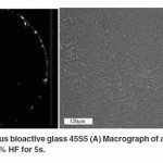
A macrograph of an as received amorphous bioactive glass 45S5 disc is shown in Figure 1A which indicates a completely transparent sample. Moreover, an optical micrograph of an etched amorphous sample (Figure 1B) produces a rough surface due to etching of impurities or discontinuities on the surface. Images were obtained after the samples were treated as per the procedure mentioned by Kashyap et al.
Crystallization of bioactive glass 45S5 at 680°C
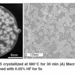
Partially crystallized sample Macrographs and optical micrographs of bioactive glass 45S5 sample crystallized at 680°C for 30 min is shown in Figure 2.29 Crystalline phase growing in an amorphous matrix was observed which indicated ‘devitrification’ occurring in these samples. Moreover, as evident from the optical micrographs in Figure 2B, growth of crystals continued with increasing crystallization times until they impinged on one another. Another observation made was the emergence of ‘flowery patterns’ inside in the partially crystallized sample as is evident from the macrograph in Figure 2A. Images were obtained after the samples were treated as per the procedure mentioned by Kashyap et al.,29.
Formation of ‘flowery patterns’ during crystallization
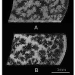
After crystallization heat treatment it was observed that apart, from changes in the optical properties due to devitrification (transparent to translucent), optical properties were also changed at random locations in the samples due to the formation of “flowery patterns” inside the glass ceramic which contributed to lower transparency in these locations by greater light scattering. Figure 3 shows an example of these flowery patterns formed in a bioactive glass 45S5 sample partially crystallized at 680°C for 30 minutes under reflected (Figure 3A) and transmitted lighting conditions (Figure 3B).
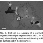
During and after polishing it was found that the sample surface contained pit like structures which were difficult to grind/polish off and seemed to be deep as is evident from the optical micrographs in Figure 4 which were taken slightly over focused in order to highlight the pits and some bright parts on the subsurface around the pits.
SEM Analysis
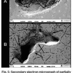
Secondary electron micrographs of these pit like structures in unetched partially crystallized sample (Figure 5A) indicated that these might be interlinked voids formed in the sample since the morphology of these pit like structures showed elongated pits and even deeper holes present at the bottom of the pit as if it was interlinked with another pit through this hole. This became more prominent in the SEM image of the pit like structures in an etched sample (Figure 5B) as it showed the pits forming at the edges of grains indicating that these depressions on the sample surface could be inter linked voids. Such voids may have formed due to shrinkage in the sample during crystallization. Due to bulk nature of the sample which hinders easy deformation, and nucleation/growth of a cluster of grains at isolated random locations, these voids were formed as a result of crystals forming and causing shrinkage along its peripheral areas, thus forming interlinked voids along the grain boundaries.
Dye Penetrant Test Analysis
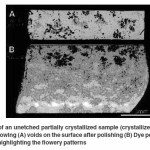
In order to correlate the interlinked voids on the sample surface found after polishing with the “flowery patterns” that were seen in the macrographs, dye penetrant test was conducted. The macrograph in Figure 6(A) shows the voids present on the surface a partially crystallized sample after polishing. The corresponding macrograph of the same sample after the dye penetrant test shown in Figure 6(B) reveals that the dye had seeped through the voids on the surface to their respective ends, highlighting the “flowery patterns”. It was thus evident that the “flowery patterns” formed in crystallized bioactive glass samples were actually interlinked voids that formed “flowery patterns” at isolated locations due to shrinkage during crystallization or volatilization of grain boundary phase by creating pressure pockets. Though the flowery patterns were formed by interlinked voids found at isolated locations but they were not interlinked with other voids. Hence, only those flowery patterns, whose interlinked voids were opened to the surface, were only detected by the dye.
It was also found that the “flowery patterns” formed during crystallization which provided an added translucency and formed pits during polishing in the samples were actually interlinked voids formed beside the clusters of grains (along grain boundaries). They were likely to have formed due to shrinkage during crystallization or volatilization of grain boundary phase.
Microindentation results
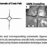
Vicker’s indentation method was employed to study the crack propagation behaviour in both amorphous and fully crystallized samples in line with that revealed earlier by Kashyap et al.,29. In case of an amorphous sample, it was observed that the Palmqvist cracks emanating from the indent tips propagated in a straight line without any hindrance. Moreover, it was also noticed that Palmqvist crack lengths for a particular indentation load were of relatively consistent length. Such an example of straight Palmqvist cracks is shown in the optical micrographs of Figure 7A which shows Vickers indents made with an indentation load of 300gf (2.940N). Figure 7B shows the utilization of Vickers indentation technique in a fully crystallized bioactive glass 45S5 sample. It was observed that the Palmqvist cracks developed in fully crystallized bioactive glass (crystallized at 680°C for 60 minutes) did not traverse in a straight line as seen in amorphous bioactive glass. On the contrary, the cracks in crystallized bioactive glass followed no particular pattern; they originated at different points all along the periphery of the indents and deflected at many points throughout the crack path. It can be inferred from this observation that the cracks might traverse through the path of least obstruction or through points where it consumed the least amount of surface energy required to form crack surfaces. Microindentation was done on these samples as per the procedure mentioned in Kashyap et al.,29. as it indicated that the interlinked voids played an influential role in the stoppage or initiation of crack path at random location during indentation.
Possible effects of ‘flowery patterns’
As shown in previous sections, the “flowery patterns” formed during crystallization of bioactive glass 45S5 were actually interlinked voids likely to have formed due to shrinkage during crystallization. Presences of these voids can possibly affect the fracture behaviour in partially crystallized sample either by acting as crack arrestors (crack propagation stops at these voids) or as stress concentrators for crack initiation. As is evident in section 3(F), the abrupt change in the crack paths, sudden stoppage of crack path (crack arresting) and occurrence of cracks at location away from the indent corners (crack initiation) in a fully crystallized sample may be attributed to the interlinked voids present in it. Moreover, rise in the thermal shock resistance of a partially crystallized sample on quenching in water from 680°C observed by Kashyap30 may be also an effect of these inter-linked voids. Stress concentration at these voids might aid in micro-cracking on quenching the partially crystallized sample from 680°C to room temperature. In both the cases, an increase in the toughness is expected if crack propagation is restricted in the first case while numerous micro-cracks formed would induce toughening in the second case.
Conclusions
In an effort to study the crystallization behaviour of bioactive glass 45S5, it was observed that in addition to the ‘devitrification’ produced as a result of crystallization heat treatment; ‘flowery patterns’ formed inside the sample. On further analysis of these flowery patterns under optical and scanning electron microscopy along with dye penetrant testing, it was proved that these were actually interlinked voids formed inside the bioactive glass sample during crystallization. Shrinkage occurring as a result of crystal formation may be attributed to the formation of these voids along the periphery of the crystal grain boundaries. Moreover, these inter linked voids may also induce toughening in bioactive glass by contributing to the increase in the thermal shock resistance of a partially crystallized sample, abrupt crack path stoppage and crack initiation at locations away from the indent corners of a fully crystallized sample by acting as crack arrestors.
Acknowledgements
The author would like to thank Dr. John A. Nychka (Department of Chemical and Materials Engineering, University of Alberta, Canada) for his guidance and laboratory facilities. Special thanks to Mr. Ted Day, Mo-Sci Corporation for supplying the bioactive glass 45S5 rods and material data. The author would also like to thank and De-ann Rollings (University of Alberta) for SEM work
References
- Temenoff, J. S., Lu L., and Mikos A. G., Bone-tissue engineering using synthetic biodegradable polymer scaffolds, Bone Engineering, Em squared Inc., Toronto 454 (2000).
- Bruder, S. P., and Caplan A. I., Bone regeneration through cellular engineering, Principles of Tissue Engineering 2: 682-696 (2000).
CrossRef
- Jones JR, Boccaccini AR. Cellular ceramics in biomedical applications: tissue engineering. In: Scheffler M, Colombo P, editors. Cellular Ceramics: Structure Manufacturing, Processing and Applications. Weinheim: Wiley-VCH Verlag GmbH & Co. KGaA; 550-573 (2005).1.
- Hench L. L., Glass Technol. 44(1): 1-10 (2003).
- Wilson J., Pigott G. H., Schoen F. J. and Hench L.L., J. Biomedical Materials Research, 15(6): 805-817 (1981).
CrossRef
- Oonishi H., Shoichi K., Yasukawa E., Iwaki H., Hench L.L., Wilson J., Tsuji E., and Sugihara T., Clinical Orthopaedics and Related Research, 334: 316 (1997).
- Gatti A. M., Valdre G., and Andersson Ö. H., Biomaterials, 15(3): 208-212 (1994).
CrossRef
- Clark A.E., Hench L.L., Journal of Biomedical Materials Research, 28: 693-698 (1994).
CrossRef
- Nychka, J. A., Mazur S.L.R., Kashyap S., Li D., and Yang F., JOM, 61(9): 45-51 (2009).
CrossRef
- Cao W., and Hench L.L., Ceramics International, 22(6): 493-507 (1996).
CrossRef
- Hench, L. L., J. Am. Ceramic Society, 81: 1705-1728 (1998).
CrossRef
- Li, D., Yang F., and Nychka J., Engineering Fracture Mechanics, 75(17): 4898-4908 (2008).
CrossRef
- Michel M. D., Mikowski A., Lepienski C. M., Foerster C. E., and Serbena F. C., J. Non-Crystalline Solids, 348: 131-138 (2004).
CrossRef
- Callister W.D. Jr., Materials Science and Engineering: An Introduction, John Wiley & Sons Inc. New York, USA (2007).
- Cerruti, M.G., Greenspan D., and Powers K., Biomaterials, 26(24): 4903-4911 (2005).
CrossRef
- Vogel M., Voigt C., Gross U.M., and Müller-Mai C.M., Biomaterials, 22(4): 357-362 (2001).
CrossRef
- Sepulveda P., Jones J.R., and Hench L.L., Key Engineering Materials, 192: 629- 634 (2000).
CrossRef
- Leatherman B.D., and Dornhoffer J.L., Otology & Neurotology, 23(5): 657-660 (2002).
CrossRef
- Vollenweider M., Brunner T.J., Knecht S., Grass R.N., Zehnder M., Imfeld T., and Stark W.J., Acta Biomaterialia, 3(6): 936-943 (2007).
CrossRef
- Wheeler D.L., Stokes K.E., Hoellrich R.G., Chamberland D.L., and McLoughlin S.W., J. Biomedical Materials Research, 41(4): 527-533 (1998).
CrossRef
- Boccaccini, A.R., Notingher I., Maquet V., and Jérôme R., J. Materials Science: Materials in Medicine, 14(5): 443-450 (2003).
CrossRef
- Lin C.C., Li-Chen H., and Shen P., Journal of Non-Crystalline Solids, 351(40): 3195-3203 (2005).
CrossRef
- Fuchs, G. A., Biomedizinische Technik / Biomedical Engineering, 27(1-2): 24-29 (1982).
CrossRef
- Greenspan, D. C., and Hench L. L., Journal of Biomedical Materials Research 10(4): 503-509 (2004).
CrossRef
- Vlasov A.S., and Ludanova O.V., Glass and Ceramics, 52(4): 99-101 (1995).
CrossRef
- Doremus, R.H., Glass Science, Wiley New York, (1973).
- Stookey S.D., Maurer R.D., Catalyzed Crystallization of Glass – Theory and Practice. Pergamon Press, New York, 77 (1962).
- Chen Q.Z., Thompson I.D., and Boccaccini A.R., Biomaterials, 27(11): 2414-2425 (2006).
CrossRef
- Kashyap S., Griep K., and Nychka J.A., Materials Science and Engineering: C, 31(4): 762-769 (2011).
CrossRef
- Kashyap S., “Fracture behaviour of bioactive glass ceramic: an effort to increase its mechanical properties,” in Proceedings. ICAET Conf. Pune, 44 (2013).
- Bretcanu O., Chatzistavrou X., Paraskevopoulos K., Conradt R., Thompson I., and Boccaccini A.R., Journal of the European Ceramic Society, 29(16): 3299-3306 (2009).
CrossRef
- Lefebvre L., Chevalier J., Gremillard L., Zenati R., Thollet G., Bernache-Assolant D., and Govin A., Acta Materialia, 55(10): 3305-3313 (2007).
CrossRef

This work is licensed under a Creative Commons Attribution 4.0 International License.