Synthesis, Characterization and Computational Studies of Multiwall Carbon Nanotubes
Ratnakar Pandu
S.R. International Institute of Technology, Rampally Village, Kisara Mandal - 501 301, India.
Article Publishing History
Article Received on : 29 Jan 2013
Article Accepted on : 12 Apr 2013
Article Published :
Plagiarism Check: No
Article Metrics
ABSTRACT:
This work is focused on the synthesis, characterization and computational studies of multiwall carbon nanotubes. Growth of pure carbon nanotubes have been carried out by vapor phase growth and thermal CVD methods. After optimizing the growth parameters for both methods, the multi-walled carbon nanotubes (MWCNTs) have been obtained. Best optimized temperatures are 900oC and 825oC for vapor phase growth and thermal CVD methods respectively, showing highest yield of CNTs. Average length of CNTs is around 72ìm for acetylene method, and 60ìm for xylene method for diameters range of 30-50nm. In the second stage, by using the geometrical parameters of the experimental observations, computational studies of CNTs are carried out to know the elastic bending and buckling behaviors of carbon nanotubes. A Finite Element (FE) approach has been made to analyze and study the bending deformations and buckling behavior of MWCNTs. The results calculated in this work, agree with the results of other similar numerical simulation studies available in the literature and then establishing the validity of the present FE approach. The results could be an instrument for studying the mechanical behaviors of MWCNTs and their usefulness in nanocomposite materials field. It can be used as a substitute competent method to study bending and buckling of the CNTs accurately.
KEYWORDS:
Growth of carbon nanotubes; Vapor phase growt; Thermal CVD method; Finite element; EDAX analysis; Shell93 element
Copy the following to cite this article:
Pandu R. Synthesis, Characterization and Computational Studies of Multiwall Carbon Nanotubes. Mat.Sci.Res.India;10(1)
|
Introduction
The Carbon Nanotubes are first invented by Iijima1 in 1991. Later they have fascinated almost all the scientists and researchers because of their unique properties like mechanical properties i.e., structural perfection, high strength and stiffness, low density, small in size etc.2-3 They are stronger and superior than, when compare with the performance of any other materials like steel, tungsten carbide, alloys of carbon etc. They also possess high thermal, electrical, optical and tremendous electronic properties with greater quality which any other materials cannot exhibit. The atomic graphite structure looks like one-atom thick sheets of planar network of interrelated hexagonal rings of carbon atoms. In normal graphite, carbon sheets are located on top of one another, allowing them to easily slide. Therefore, graphene sheets are very soft, and greasy. They may be used as lubricant. When a graphene sheet is rolled into cylindrical shape and edges joined together, it forms CNT. Graphene sheets are placed in such a way that only the tangents of the graphitic planes come into contact with one another. Hence, their properties are more like that of a carbon molecule. In general, a nanotube consists of only one atom thick. One graphite tube known as a Single Walled Nanotube (SWNT) and a number of concentric tubes are known as Multiwall Nanotubes (MWNTs). The SWNTs appear as two planes. Whereas MWNTs appear as more than two planes and may be observed as series of parallel lines. Because the graphene sheets can be rolled in different ways, there can be different types of CNTs. The three different types of CNTs are Zigzag, Armchair and Chiral. The SWCNTs, which consist of single layer of graphene strips and could, form multi wall nanotubes. The individual tubes in the bundle are attracted to the neighbouring ones. This attraction is due to the van der Waals interactions between the tubes. This distance between tubes may equal to the inter-planar distance of graphite i.e., 3.34 Å. An MWCNT is formed by concentric graphitic layers with or without closed caps at both ends. These layers are weakly bound by van der Waals forces. Since the graphene interlayer spacing is 3.34Å, the concentric layers in the MWCNTs are also separated by the same distances. Thus, the successive concentric layers will differ in the circumference by 2P × 3.34 ~21Å. An armchair MWCNT will have an interlayer distance between successive concentric layers of 3.4Å. The wall thickness of an N-layered MWCNT is given as t=0.314N nm, where‘t’ stands for thickness.
Literature Review
So far, the experimental research on properties of CNTs is mainly confined to their static mechanical properties like strength, bending, buckling; Young’s and Shear modulii, electromechanical coupling, mechanical resonance, and some thermal properties. The mechanical behaviors of CNTs have been the area of research of experimental studies and studies of elastic continuum modeling and Molecular Dynamics. While studying MWCNTs, reliable understanding of the tube geometry before transferring the data into properties is very important. The CNTs’ structure can be studied thoroughly by MD simulations, microscopy and spectroscopy. The scope of the present work restrict to establishment of the properties by conducting experimental work on synthesis and characterization of CNTs and simulation work by an FEA approach by modeling the structures and the deformation of MWCNTs. The small dimensions of CNTs, which are of few nanometers diameter and lengths in microns, pose challenges for experimental observation of properties and mechanical behaviors. Both SWCNTs and MWCNTs give significant promise for utilization as catalysts, as strong and super-stiff nanofibers and as components of electrical, electronic and thermal devices.4, 5 In spite of the applications of CNTs in many areas like technology and science, thorough understating of their mechanical behaviors is not available in literature. Hence, the design and optimization of CNTs are presently difficult. Treacy et al6 used transmission electron microscopy (TEM) to study the thermal vibration of cantilevered MWCNTs inside. They obtained a mean modulus of elasticity 1.8TPa with a scatter from 0.400 to 4.150TPa. Krishnan et al.,7 who made a similar study reported, Young’s modulus varying between 0.9TPa to 1.70TPa with an average value of 1.25TPa, using TEM. They observed thermal vibration of single walled CNTs. However, the length and diameter of samples of the CNTs used in the technique used by Krishnan et al. and Treacy et al. were limited to those that did not result in neither too small nor too big thermal vibrations, which were necessary for reliable TEM detection.
Wong et al.,8 got the modulus of elasticity as 1.28 ± 0.59TPa without considering the diameter of MWCNT. They used in atomic force microscopy (AFM) as a cantilevered beam for the analysis of bending. Salvetat et al.,9 proposed that the Young’s modulus can be determined by depositing the CNTs on a membrane. A CNT across pores and formed a clamped beam and they used AFM to apply load on the suspended CNT caused a deflection on the CNT based on applied force. They found Young’s modulus as 0.81±0.41TPa. Iijima et al.,10 used high resolution electron microscopy (HREM), and observed single kinks in 0.8 and 1.2nm diameter SWCNTs for large bending angles. Several researchers observed that the MWCNTs display multiple buckling patterns during bending. During the bending of MWCNTs, they used five- walled CNTs in HREM and observed single kink; then, by increasing load for further bending, they observed double kinks without change in distances between respective walls for high degree angles of bending.
For the last 15 years, SWCNTs and MWCNTs have created strong research endeavor in the search of their mechanical properties. Many studies have been made on MD simulations and Electronic simulations like ABACUS, ANSYS etc, on the deformations and structures of CNTs. The results indicate that, if wall modulus and thickness are properly defined the nanotube walls may be treated as elastic shells without much lose of accuracy. The results also revealed that, at a certain level, SWCNTs could be treated as beams of effective bending stiffness. Robertson et al.11 studied energies of many SWCNTs with radii < 0.9nm using both theoretical and experimental methods. They understood that CNTs hold internal strain energy per carbon atoms comparable to the unstrained graphitic sheet which has an inverse square (1/R2) dependence on CNT radius. It is not sensitive to other properties of lattice structure, even when tube radius is 0.35nm. This result agrees well with the results using continuum elasticity theory. They assumed the wall thickness to be 0.314nm, which is equal to the graphite inter-planar spacing. They compared their results to the results obtained from beam theory. Kundin et al.12 calculated the poison’s ratio (í) in plane and bending stiffness of CNTs using ab initio energy calculations. The value of í was computed from the reduction in diameter of the CNTs under simulation. They compared the in- plane stiffness and the bending stiffness relations for isotropic continuum shells to the ab initio results, and obtained the values Ewall=3.859TPa; twall=0.0894nm. Born and Huang13 derived elastic constants based on the potential energy of a crystal system. Martin’s approach is also called the Cauchy- Born hypothesis. Using the Cauchy-Born rule Zhang et al.,14,15 proposed a nanoscale continuum theory. CNTs are made up of curved atomic layers. They pose a big challenge in the simulation of CNTs using Cauchy-Born rule.This application may cause inconsistency in the mapping. By introducing the concept of exponential mapping from differential geometry, Arroyo and Belytschko16 corrected this inconsistency. Buehler et al.,17 investigated the SWCNTs subject to compression load and found a shell-rod-wire transition of the mechanical behavior of CNT with increasing aspect ratio. They revealed that wire-like CNTs could form attracting each other through vdW forces. Liew et al.,18 investigated the tensile properties of CNTs and obtained the stress- strain responses and the mechanical properties for 1 to 4-walled CNTs.
Growth Of Carbon Nanotubes Through Experimental Methods
Carbon nanotubes are grown by two different methods, one by using Xylene (Thermal CVD) as a carbon source while other using Acetylene (Vapor Phase Growth) as a carbon source. For both the methods iron as catalyst and Ferrocene as iron precursor are used.
Thermal CVD Method
The apparatus mainly consisted of a simple atomizer that had two inlets: one for the carrier gas Ar/H2 and the other for the liquid reactant. Approximately the Ferrocene with 6.5 mol% was dissolved to get a feed solution with 0.75 At% Fe/C ratio, in xylene. It was fed into the atomizer continuously through the dripper, which had a flow control wheel, into a tubular quartz reactor (diameter 30mm, length 60cms). The reactants were held in an injector and gave out through a pine needle into the dripper. Ar/H2 gas flow was optimized in such a method that the liquid was able to reach the centre of the furnace. H2 is required for the reduction of xylene. To produce catalyst Fe particles, which can generate nanotube growth, Ferrocene, whose catalyst main particles (sublimation temperature is 140°C) has been shown to be a high-quality precursor. Xylene is selected because the hydrocarbon source boils (boiling point, 140°C) under the decomposition temperature of ferrocene (~190°C).
The liquid feed was passed through a medical nebulizer, which was used as an atomizer, attached to the quartz tube (preheated to the desired temperature), into the furnace. The atomizer is inserted into the tube and the junction is properly insulated to air by a Teflon tape in order to prevent oxidation of iron. Contact with oxygen can also lead to a minor flame. The tube is heated using a cylindrical furnace with a precise temperature control. The liquid leaving the tube quickly volatilized at the temperature and sweep up into the zone of reaction of the furnace by a stream of argon with 5% hydrogen. The furnace temperature (750–900°C), feed rate (0.5-2mL/min) and sweep gas flow pressure (1-2 kg/cm2) are used to examine the growth conditions meant for high purity associated MWCNTs, keeping the ferrocene/xylene ratio (6.5mol %) constant. The growth parameters are optimized to obtain the final sample. The final sample is at following conditions; 825°C temperature, 1.5mL/min feed rate, 1.5kg/cm2 Ar/H2 gas pressure. When the reaction is completed, the furnace is allowed to cool up to room temperature in stream of Air or Hydrogen. During growth, nanotubes begin to form in the vapor phase, then deposit on the quartz tube walls. The sample formed inside the tube is immediately annealed to remove left out iron in the form of its oxide at the experimental temperature. After the room temperatures are attained, the sample is found to form a cylinder along the tube axis and it be supposed to carefully scratched out.
Vapor Phase Growth Method
Apparatus used in this method is same as used in Thermal CVD method, but the difference is of carbon source, now, Acetylene is used as a carbon source in place of Xylene. Ferrocene is used as iron precursor and put at the inlet of the tube. In this method we have also optimized the growth condition by changing growth parameters; reaction temperature and Acetylene flow rate. The temperature is changed from 800-900°C and acetylene pressure to 0.2-0.5Kg/cm2. To obtain the inert atmosphere in the tube to prevent oxidization of Ferrocene and fire, flow the Ar gas before the flow of acetylene. In the reaction zone both Ferrocene and acetylene decomposes to form CNTs. Final conditions for carbon nanotube growth is 900°C temperature and 0.2 Kg/cm2 acetylene partial pressure. As growth conditions matched then get black carbon nanotube powder in the reaction zone and that is carefully peeled off for further characterization.
Purification Of CNTs
As formed carbon nanotubes have impurities of catalyst particles and amorphous carbon. The raw particles, amorphous carbon, and multi-shell carbon material are first heated in Ar/H2 atmosphere to remove them. After room temperature is attained, the powder form of the tubes is collected. For purification purposes it is dissolved in 6M nitric acid for 12hrs, and after washing it with distilled water, black powder putted in to the oven at 150°C for drying. After drying the sample heated in the nitrogen environment at 300°C for 4 hours. The final product is now ready for characterization.
Modeling Of Multiwall Carbon Nanotubes
By taking geometrical parameters obtained from experimental results, the 13, 14 and 15 walled CNTs are modeled using eight nodded shell93 element. Elastic shell theory can be derived for structures with 1D’s (thickness of the wall) extremely lesser than the other 2D’s, gives a natural approval for CNT that can be an idea of single graphene sheet of hexagonal lattice structure that may be enfolded into a continuous and perfect cylinder with no damage.
Description For Geometrical Modeling Of The MWCNTs
As geometric dimensions of the CNTs are very small, even a small error is not tolerated. To build the CNT model accurately eight nodded shell93 elements are used. The inner diameter of the first tube is taken as 0.34nm, the tube’s wall thickness and the gap between two successive tubes is 0.314nm, which is equal to distance between two successive carbon atoms. In this work carbon nanotube is analyzed and assumed it as a cantilever beam. The beam is modeled using shell93 element. The shell element is having 6 degrees of freedom at each node. In modeling the MWCNT, one end is fixed and load is applied at the free end. The thickness of each tube wall has been given in the real constants as 0.314nm. From the above literature, Young’s modulus (E) is taken as 4.48TPa and an assumed Poisson’s ratio (í) is 0.2. The length of tube consider as 100nm and density as0.14g/cm3. Load assumed as 10nN for analyzing 13, 14 and 15 walled CNTs. Finally, after solution is obtained, the results of first set have been taken from each type of MWCNTs and analyzed in detail.
Results And Discussions
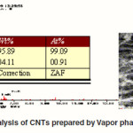
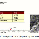
EDAX Analysis
The chemical compositions of the synthesized samples are clearly indicated by the Energy Dispersive Analysis of X-ray (EDAX) presented in Fig.1. It is to be noted that the percentage of catalyst Fe in the sample prepared by Vapor phase growth method is less than as prepared by Thermal CVD method, indicating high purity of the CNTs. The focused EDAX on a single tube for each sample clearly indicates the highest Wt% and At% of C in the sample prepared by Vapor phase growth method at 900°C with Acetylene and 825oC with xylene. Best optimized temperatures are 900oC and 825oC for vapor phase growth and thermal CVD methods respectively, showing the highest yield of CNTs. Average length of CNTs is around 70ìm for acetylene method and 60ìm for xylene method for the diameters range of 30-50nm. Also the outer CNTs’ diameters calculated ranges from 32 to 80nm. The EDAX investigation revealed that the CNTs grown by the Vapor phase growth method are well aligned, high yield and highly purified as compared to CNTs grown by Thermal CVD method. Therefore, acetylene is better hydrocarbon source as compared to xylene.
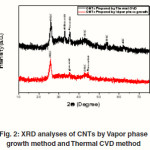
Analysis Using XRD And EDAX
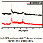
The XRD technique was used to characterize the crystalline structure of the samples. XRD patterns of the CNTs prepared by Thermal CVD and vapour phase growth are presented in Fig. 2 (a) and (b) respectively. It is observed that the characteristic diffraction peak (002) of MWCNTs located at 2u = 26.0° in both samples consistent with the reports.19 Comparing the relative intensities of C (002) and other impurity peaks, we can clearly see that the most prominent peak is C(002) that confirms the sample prepared is carbon nanotubes. The CNT sample prepared by Thermal CVD method has some additional peak due to presence of amorphous carbon and metal catalyst but sample prepared by Vapor phase growth method is relatively pure. It is also seen the effect of nitrogen flow over the sample prepared by Acetylene method. Fig. 3(a) and (b) clearly shows the effect of nitrogen flow, some impurity peaks in XRD pattern have been suppressed after the nitrogen flow. This confirms that CNTs have been purified due to flow of nitrogen.
Simulation Studies On Bending Behavior Of MWCNTs
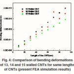
Using geometrical parameters of the above experimental results and other properties of CNTs, the simulation studies on MWCNTs were carried out. In the present work, the bending and buckling of MWCNTs is broadly simulated by the FEA approach using ANSYS11.0. The analysis includes the influence of nanoscale effect and layer number on the critical bending and buckling load of MWCNTs. As a first step 13, 14 and 15 walled CNTs are modeled using shell93 element and meshed with fine mesh as applicable for structural shell element in the ANSYS11.0. The loading and boundary conditions, and deformed (total deformation) shapes of these CNTs are simulated. The maximum deformations (DMX) along X- direction of the tubes known from the simulation are 0.200E-9nm, 0.178E-9nm and 0.146E-9nm for 13, 14 and 15 walled CNTs respectively. Similarly, the maximum deformations (DMX) along Y-axis are 0.201E-9nm, 0.174E-9nm and 0.146E-9nm for 13, 14 and 15 walled CNTs. Fig.4 shows the comparison at bending deformations of 13, 14 and 15 walled CNTs for the same length and applied load. The graph is plotted between bending deformation vs. length of CNTs. Only 14- walled CNT has slightly differed from other two CNTs plotted on the graph. All three CNTs are giving linear curves.
Simulation Studies On Buckling Behavior Of MWCNTs
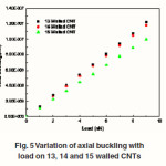
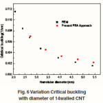
It is experimentally observed that for the three MWCNTs, the diversity of flexural moment gives non-linearity for smaller bending angle, which is different from that the SWCNTs, presented earlier. The non-linearity of MWCNTs is due by the interlayer van der Waals forces. By additional increase in the angle of bending, flexural moment alters with the linearity of angle of bending. When the flexural moment reaches the angle of critical bending, it stops its development. With still additional increase in angle of bending, the flexural moment goes down suddenly, and MWCNTs come up to post-buckling condition. It reveals that the post buckling equilibrium path of MWCNTs due to bending load is not stable. It may be observed that with the increase in MWCNTs inner-tube, the critical flexural moment increases clearly while the angle of critical bending and critical curvature of bending-buckling reduces. Fig.4 shows the change in curvature of critical buckling with the diameter of MWCNTs. For curve fitting, it is also noted that, for 13, 14 and 15walled MWCNTs with same length, the critical buckling curvature goes down as Inverse Square of the tube’s diameter. From the graph (Fig.5) it is observed that the buckling effect on 13, 14 and 15 walled CNTs are almost linear for the same length and load applied, irrespective of their outer diameters. Fig.6 shows the change of critical buckling curvature with the diameter of CNTs. It is observed that, for all different MWCNTs, with equal length, the buckling curvature changes with Inverse Square of the tube diameter.
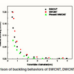
The correlation between critical buckling curvature and nanotube diameter for SWCNT, DWCNT and MWCNTs are compared and shown in Fig.7. Further, it is revealed that the critical buckling curvatures for SWCNT, DWCNT and MWCNT are approximately identical for the diameters d>4nm. The critical buckling curvatures for SWCNT is more than that of DWCNT and MWCNTs for diameters d<4nm. The sound effects of different layers on the buckling property of MWCNTs are studied by applying the present customized F.E.A method. The geometrical configurations for 13, 14 and 15 walled CNTs with Length = 100nm at the preliminary buckling position shows the 3D integral buckling deformation of MWCNTs. The shape of the proportioned plane in Fig.4 shows that the inter-layer spacing of MWCNTs have no observable effect during the bending position under the action of von der Waals (vdW) forces.
Conclusions
To develop high quality nanomaterials such as Carbon Nanotubes for specific uses, it is necessary to understand various phenomena concerning electrical and structural properties of the materials. The aim of this paper is focused on the synthesis, characterization and simulation studies of Carbon Nanotubes. Growth of pure carbon nanotubes have been carried out by vapor phase growth (acetylene) and thermal CVD (xylene) methods. After optimizing the growth parameters for both methods, the multi-walled carbon nanotubes have been obtained. Best optimized temperatures are 900oC and 825oC for vapor phase growth and thermal CVD methods respectively, showing highest yield of CNTs. Average length of CNTs is around 72µm for acetylene method and 60ìm for xylene method and diameters range of 30-50nm.
Using the above geometrical properties, simulation studies of MWCNTs are carried out to know the elastic bending and buckling behaviors of carbon nanotubes under bending loading and axial compression load. An F.E approach has been made to analyze and study the bending deformations and buckling behavior of multi walled CNTs. The results calculated for the MWCNTs agree with the results of other similar numerical simulation studies available in literature and then establishing the validity of the present Finite Element approach. The analyses have been performed using ANSYS 11.0. The structure of MWCNT is assumed as cantilever and loaded at the free end. Definite relationship is developed between the diameter and the critical buckling curvature of the CNTs. The deviations of bending load with bending curvature meant for the CNTs with dissimilar geometric constraints like different diameters of the CNT and lengths are analyzed in detail. Results of the analysis confirm the present F.E technique could be a helpful instrument for studying the mechanical behaviors of MWNTs as distinct units, and their usefulness in the field of nanocomposite materials. Finally, it seen that the present FEA approach is faster in computation. It can be used as a substitute competent method to study bending and buckling of the CNTs accurately.
Acknowledgements
The first author expressing his deep sense of gratitude towards Smart Materials Lab IIT- Roorkee and Concurrent Analysis Corporation – Hyderabad for providing experimental and computational facilities respectively.
References
- S Iijima, Helical microtubules of graphitic carbon, Nature, 354: pp56–58 (1991).
- P. J. F. Harris, “Carbon Nanotubes and related structures”, Cambridge University Press (1999) .
- Smolenski G A & Chupis I E, “Ferroelectromagnets”, Usp. Fiz. Nauk, 137: 415 (1982).
CrossRef
- Dreselhaus, M.S. Dreselhaus, G., Avouris, P., Carbon Nanotubes. Springer, Heidelberg (2001).
- Chopra N.G, Benedict L.X, Crespi VH, Louri SG, and Zettl A, “Fully Collapsed Carbon Nanotubes”, Nature (London), 377: pp135- 138 (1995).
- Treacy MMJ, Ebbesen TW, and Gibson JM, “Exceptionally high Young’s modulus observed for individual carbon nanotubes”, Nature (London), 381: pp678-680 (1996).
CrossRef
- Krishnan A, Dujardin E, Ebbesen TW, Yianilos PN, and Treacy b MMJ, “Young’s modulus of single-walled nanotubes”, Pysics Review B, 58: pp1 4013-14019 (1998).
- Wong EW, Sheehan PE, and Lieber CM, “Nanobeam mechanics: Elasticity, strength, and toughness of nanorods and nanotubes”, Science, 277: 1971-1975 (1997).
CrossRef
- Salvetat JP, Bonard JM, Thomson NH, Kulik AJ, Forro L, Benoit W, and Zuppiroli L, “Mechanical properties of carbon nanotubes”, Applied Physics A, 69: pp255- 260 (1999).
- Iijima, S., Brabec, C., Maiti, A., Bernholc, J., ,”Structural Jexibility of carbon nanotubes”,J. Chem. Phys. 104 (5): pp2089 2092 (1996).
- Robertson, DH., Brenner, DW., Mintmire, JW., “Energies of nanoscale graphitic tubules”, Phys. Rev. B, 45(21): pp12592-12595 (1992).
- Kundin, K.N., Scuseria, G.E., Yakobson, B.I., “C2F, BN, and C nanoshell elasticity from ab initio computations”, Phys. Rev. B 64: pp235406 (2001).
- Born, M., Huang, K., “Dynamical Theory of Crystal Lattices”, Oxford University Press, Oxford (1954).
- Zhang, P., Huang, Y., Gao, H., Hwang, K.C., Fracture nucleation in single-wall carbon nanotubes under tension: continuum analysis incorporating inter-atomic potentials. J. Appl. Mech. Trans. ASME 69: pp454 – 458 (2002a).
CrossRef
- Zhang, P., Huang, Y., Geubelle, P.H., Klein, P., Hwang, K.C., “The elastic modulus of single-wall carbon nanotubes: continuum analysis incorporating inter-atomic potentials”. Int. J. Solids Struct. 39: 3893– 3906 (2002b).
CrossRef
- Arroyo, M., Belytschko, T., “An atomistic- based membrane for crystalline 3lms one atom thick”. J. Mech. Phys. Solids 50: pp1941–1977 (2002).
CrossRef
- Buehler MJ, Kong Y, and Gao H, “deformation Mechanisms of very long single-wall carbon nanotubes subject to compressive loading”, J Eng Mater Tech, 126: pp245-249 (2004).
CrossRef
- Liew KM, He XQ and Wong CH, “On the study of elastic and plastic properties of multi- walled carbon nanotubes under axial tension using molecular dynamics simulation”, Acta Mater, 52: pp2521-2527 (2004a).
CrossRef
- P. Chen, X. Wu, J. Lin, K.L. Tan, “High H2 Uptake by Alkali-Doped Carbon Nanotubes under Ambient Pressure and Moderate Temperatures” Science 285: 92 (1999).
CrossRef

This work is licensed under a Creative Commons Attribution 4.0 International License.