Performance and Thermal Analysis of Aluminium Oxide Filled Epoxy Composite as TIM for LEDs
Nur Jassriatul Aida Binti Jamaludin, P. Anithambigai, S. Shanmugan, D. Mutharasu
Nano Opto Electronics Lab (NOR), School of Physics, Universiti Sains Malaysia (USM), 11800 Minden, Penang, Malaysia.
DOI : http://dx.doi.org/10.13005/msri/110105
Article Publishing History
Article Received on : 25 Aug 2014
Article Accepted on : 02 Sep 2014
Article Published : 08 Sep 2014
Plagiarism Check: Yes
Article Metrics
ABSTRACT:
Al2O3powder with various particle sizes was prepared by milling process and mixed together with epoxy resin in order to increase the thermal conductivity of resin and decrease the junction temperature of the LEDs. Al2O3 powder filled epoxy resin was applied as thermal interface material (TIM) for an effective system level analysis of thermal transient measurement. The result depicted that the milled Al2O3 powder for 3 hour powder showed the highest thermal conductivity and hence lower in thermal resistance of LED. Moreover, the driving currents also influence the thermal resistance and achieved low thermal resistance when measured at 350mA. The thermal properties of the sample were tested using t3ster. The surface morphology of the samples was tested using FESEM.
KEYWORDS:
Al2O3 powder; thermal resistance; thermal conductivity; surface analysis;
Copy the following to cite this article:
Jamaludin AN. A. B, Anithambigai P, Shanmugan S, Mutharasu D. Performance and Thermal Analysis of Aluminium Oxide Filled Epoxy Composite as TIM for LEDs. Mat.Sci.Res.India;11(1)
|
Copy the following to cite this URL:
Jamaludin AN. A. B, Anithambigai P, Shanmugan S, Mutharasu D. Performance and Thermal Analysis of Aluminium Oxide Filled Epoxy Composite as TIM for LEDs. Mat.Sci.Res.India;11(1). Available from: http://www.materialsciencejournal.org/?p=549
|
Introduction
Thermal management problem had increased for the demand in the design of a better quality of the thermal issues. Thermal interface material is one of the solutions to solve the problem and it is designed to fill in the air gap and irregularities for better heat management and increase the performance of the device [1-3]. Without the thermal interface material, the heat flow through the joint of the material face slowly, thus the thermal conductive performance of the device is bad. By adding the thermal interface material to link the two surfaces together, the heat dissipation performance will be in a good state.
In short, heat dissipation has to become a reason that which affect the performance and reliability of LEDs. Basically, LEDs are encapsulated in transparent resin, which has low thermal conductivity. The heat produced from the device is conducted through the back side of the chip which is possible by introducing a thermal interface material with good thermal conductivity. That is why thermal management is crucial in LEDs technology. TIM is a substance that reduces the contact thermal resistance at the interface by filling microscopy air-gaps present due to the imperfectly flat and smooth surfaces of the component [3]. TIM is those which are useful for establishing an effective thermal oath between a heat-generating component and a heat –sink attached to it [4]. The first tactic in overcoming this barrier is to fill the voids and eliminate air by introducing a third material to the heat path that is fluidic and wets the surfaces. For more demanding thermal application, the second tactic is use to use composite TIM containing filler that enhance the conduction process of the third material [5]. An ideal TIM must possess a high thermal conductivity and low coefficient of thermal expansion (CTE).
Several TIM materials are available in the market, among them the importance has been given to paste type material since it performs well to reduce the device heat considerably as a result of conformability and their fluidity. But, the currently using pastes or resins are having low thermal conductivity and could not be applied for high power devices. In this study, Al2O3powders have been chosen to be the filler of the thermal interface material. Al2O3 is an excellent thermal and electrical insulator. Additionally, it is extremely resistant to wear and corrosion. Effect of different particle size of Al2O3 powder was tested in order to investigate the suitable particle size that can increase the performance of the heat dissipation for the LED.In this method, the Al2O3 powder as a filler and the polymer are mixed together by physical method and used as TIM. By mixing with certain ratio of filler and polymer, the conductivity of material will be improved. In this research work,
Aluminium oxide of different particle size was mixed together with epoxy resin and was tested as thermal interface material for high power LED. This is to investigate the improvement in the heat dissipation mechanism of the system. The effective heat dissipation has been discussed extensively in term of the effect of particle sizes of the filler and the effect of current on the TIM.
Experimental works
Al2O3 powder (99.5% trace of metal basis) was purchased from Sigma Aldrich with average particle size of 10. 6 different sizes of alumina particle were prepared by milling process. Milling process was carried out using Ball Mill (Make: CAPCO and Model 9). In order to prepare different size of particles, the various milling time was used as 60 minutes, 120 minutes, 180 minutes, 240 minutes, 300 minutes and 360 minutes. In order to get good dispersion into polymer solution and prevent bubble forming, the mixing of alumina powder of different particle size with epoxy polymer solution was performed by using polymer mixer (Make:Thinky Mixer machine, Model: ARE-310)
In this study, novolac resin polymer was purchased from Orient Technology Sdn. Bhd and used to mix with the alumina powder. The received resin was conditioned by mixing some chemicals. Mixture of 40g of the Al2O3 filled epoxy was carried out by mixing 20g of Al2O3 powder with 20g of epoxy resin mixture. In the preparation for the mixture, the epoxy mixing was done by two part system, Part A and B. In Part A, the novolac epoxy resin and BYK-W 980 additive was mixed with speed 220 rpm for 10 minutes (make: mechanical stirrer, Model: IKA RW 20 digital) in the presence of heat @ 70℃ using ceramic heating plate, IKA C-MAG HS 7 to minimize the air bubble formation. The mixture then left aside to cool down to room temperature. In Part B, the mixture of Methylhexahydrophthalic anhydride (MHHPA) and 1-Methylmidazole was mixed with speed 220 rpm for 10 minutes in the absence of heat due to the present of catalyst. Next, part B was poured into part A and mixed for another 10 minutes so that the mixture is well incorporated with the other. The thermal interface material (TIM) was then proceeded with casting, dispensing of TIM onto LEDs and curing process.Total mass of the mixture prepared in this experiment was approximately 20 g, with the ratio of the composition is 100:85:1:1 for resin: MHHPA :BYK: catalyst. The composition and mass used in the experiment for 20g of mixture are shown in table – 1. Copper was used as substrate and cut into 5 mm x 5 mm using a substrate cutter machine. The substrate was than cleaned by ultrasonic cleaning method using wise clean machine. Copper act as a substrate that was attach together using the filled epoxy resin with the LED.
Table 1 shows the substance that was used in the mixing of the filled epoxy.
|
Material
|
Composition
|
Mass (g)
|
|
Novolac epoxy resin
|
100 %
|
10.695
|
|
Methylhexahydrophthalic anhydride (MHHPA)
|
85 %
|
9.091
|
|
BYK-W 980
|
1 %
|
0.107
|
|
1-methylimidazole (catalyst)
|
1%
|
0.107
|
Preparation of sample
Al2O3 filled epoxy was prepared by mixing Al2O3 powder to the epoxy polymer solution (Make: Thinky mixer, Model ARE-310).The ratio of filler to the epoxy resin solution is fixed as 1:1and the total weight of the mixture (epoxy and filler) is fixed as constant as 40g for each sample. The sample mixture was then cured in an oven at 180 for the first 60 minutes followed by post curing at 145℃ for 120 minutes. Next, the Al2O3powder mixed resin was then dropped onto the cleaned Cu substrate and attached to the high power LEDs. In this study, golden dragon LEDs was used and electrode wire was soldered for thermal transient measurement.
Characterization
The surface morphology and polymer homogeneity after mixing was verified by Field Emission Scanning Electron Microscope (FESEM). Thermal conductivity test was carried out for all alumina mixed epoxy samples employing Thermal Constant Analyser TPS 2500 S. In this work the sensor material utilized to study the thermal conductivity was a mica sheet. The dimensions of cured Al2O3 filled epoxy composites were 10 x 20 x 4mm cuboids and the kapton sensor was sandwiched between the samples. All the thermal conductivity measurement was measured at 25°C with heating power of 0.1W. The test time was varied from 20 to 40s based on the sample compatibility. The synthesized TIM was applied on the LED package and the package level thermal testing was carried out using Thermal Transient Tester (T3Ster). The measurement was carried out at driving current 350 mA at operating temperature of 25°C.
Results and discussions
Effect of particle size of Aluminum oxide powder
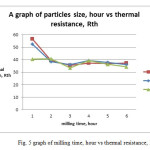
For this test, six different particle size of Al2O3 powder were prepared by varying the milling time and used in this analysis. As the milling time increases the size of Al2O3 particle decreases [11]. The effect of particle size of alumina oxide powder on the total thermal resistance of given LED and the thermal conductivity of alumina powder mixed resin was tested.
To study the thermal transient analysis, the device driving current was fixed as 350 mA and the heating and cooling transient was set for 600 s each. From the transient thermal analysis, the cumulative structure function was derived from the transient cooling curve for the given LED.Fig. 2 shows the cumulative structure function of LED attached on TIM applied Cu substrate where different particles size of Al2O3 filled epoxy acted as TIM. As reported from S.Zhanget. al, the smaller particle size, are able to increase the thermal conductivity of composite’s [6].
From fig. 2, it is observed that the alumina powder milled at 3 hrs duration show good performance on reducing the thermal resistance, Rth value of the given LED than other milling time. It is also noticed that the 2 hrs milled samples restrict the heat flow within the mixed epoxy resin and hence the Rth value was high (40.75 K/W) for the LED sample using TIM with 2 hrs milled alumina powder mixed resin.It was observed from fig. 2 that the Rth of the LED using 3 hour sample achieved the lowest thermal resistance of 33.40 K/W. It has been found that the larger particles with a thicker conductive path, thus the interfacial phonon scattering between the matrix and the filler will be reduced and hence the increased thermal conductivity is achieved for the composite. Consequently, due to the increase in the contact area and the interfacial thermal resistance which become increasingly dominant as the particle become smaller [7,8]
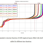 |
Fig2: the cumulative structure function of LED employed epoxy filled with Al2O3 powder milled for different time durations
Click here to View Figure
|
It can be observed that the trend (increasing particle size and decreasing contact resistance) was not in good sequences as it does not follow the theory as reported previously. This result can be explained by taking consideration on the inter-particle distance and aggregation of the particles [6]. When the composition of the Al2O3 particles in the polymer matrix increases, the average distance between the particles gets smaller, and it is possible for the formation of agglomerates in the polymer matrix. As the average of inter-particle distance getting even smaller, the rate of formation of agglomerates will also increase, thus it will result in the formation of the local alumina network.
Particle milled for 3 hrs has good contact conductance when it is filled in the polymer and hence the low Rth is desired for the matrix and high thermal conductivity is achieved. This result may be due to the low agglomerates that were present in the TIM. Besides, it can be said that 3 hour milled Al2O3having uniform particles size when compared to the other milling times. Thus, it gives the best result.
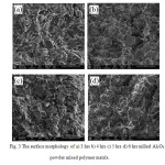 |
Fig3: The surface morphology of a) 3 hrs b) 4 hrs c) 5 hrs d) 6 hrs milled Al2O3 powder mixed polymer matrix.
Click here to View Figure
|
The dispersion of the particles differs with particles size even the content is the same. Fig. 3 a), b), c) and d) show the SEM micrograph of the composites with the particles prepared from 3, 4, 5, and 6 hours milling time respectively. As observed from Fig. 3, the dispersion in the composite changes with content for a certain size of alumina particles.
From the SEM images, it can be observed that the particle sizes of Al2O3 powder are getting smaller as the milling time increases. Fig. 3a) shows that the particle was dispersed uniformly in the matrix without serious aggregation. The large number of holes can be observed for 3 hrs milled Al2O3 particles mixed resin. As a result of milling time increases, the particle size is expected to decrease and it is possible to make uniform dispersion of the matrix with minimum number of holes. Fig. 3b) shows that, the particles were contacting each other. No serious agglomeration is observed in 4 hrs milled alumina filled matrix. Holes can be seen from the fig. 3b) but as compared to fig. 3c), the agglomeration that forms are less than that for 5 hrs milled alumina filled matrix. In fig. 3c) it can be observed that there were agglomerations present in the sample. This might be due to the smaller inter-particle distance between the particles. Fig. 3d) shows that, the number of holes are lesser compared to the other samples. The average inter-particle distance reduces with the decreases of particle size, and smaller particle size affords more connected alumina particle. Fig. 3c) and 3d) show that the dispersion is quite different and hence the aggregated particles are coexisted. These aggregations occur due to the large specific surface area and high surface energy [6].
Effect of driving current on the Al2O3 filled epoxy
Fig. 4 shows the cumulative structure function of LED employed epoxy resin as TIM with 3 hrs milled Al2O3powder as filler for different currents. Epoxy resin with 3 hrs milled Al2O3powdersample is considered in this comparison as it has highest thermal conductivity and the lowest thermal resistance.
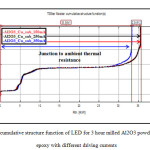 |
Fig4: cumulative structure function of LED for 3 hour milled Al2O3 powder filled epoxy with different driving currents
Click here to View Figure
|
For this test, the driving current was increased from 150 to 350 mA at the interval of 100 mA at ambient temperature of 25°C. As observed from fig. 4, the transient of all three samples follow the same pattern from the junction to the ambient. This shows that the thermal interface material has insignificant effect on Rth as driving current increases.
As the input current increases, the current density at the chip of LED will be increased 2-3 orders of magnitude higher than the other region [9]. The remarkable temperature non-uniformity in the die that is produced from the current crowding effect, affects the conductivity of the contact layer at the chip level. This effect is due to the self-heating of the device. Thus, it can be said that current crowding is the main mechanism responsible for the rise in the thermal resistance of the LED [12].
Fig. 5 shows the change in thermal resistance, Rth of Al2O3 filled epoxy for different driving currents and milling times. According to the graph, the trend shown by the currents are the same for every current. This shows that increasing in driving current does not affect the thermal resistance of the sample due to the local joule heating effect caused by the current crowding in the layer when a high current is injected. Joule heating effect, also known as ohmic heating and resistive heating, is the process by which the passage of an electric current through a conductor releases heat. The amount of heat released is proportional to the square of the current [10].
As observed from Fig. 5, Al2O3 powder that was milled for 3 hour has the lowest Rth value. 3 hour milled powder mixed resinsample is considered being the uniform size compared to the other samples. It has been reported that the heat transport ability is high when the particle are smaller in size. Smaller particles lead to lower inter-particle distance which allows the heat transfer more efficient for a system that has large interfacial area [6].
Thermal conductivity test
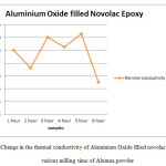 |
Fig6: Change in the thermal conductivity of Aluminium Oxide filled novolac epoxy for various milling time of Alumna powder
Click here to View Figure
|
The thermal conductivity of Al2O3 powder filled epoxy resin was measured and plotted against for various milling time of Al2O3 powder as shown in fig. 6. From the graph, it can be observed that the thermal conductivity were gradually increases for 1 hr, 3 hrs and 5 hrs. A sudden drop in the thermal conductivity was noticed for the resin with Al2O3 power milled for about 2 hrs, 4 hrs and 6 hrs. Especially, a drastic reduction on thermal conductivity was observed for 6 hrs milled powder mixed resin. As stated before, the smaller inter-particle distance is possible with the smaller size particle, thus, the thermal conductivity should be higher as the heat dissipation were more efficient in this condition. The significant drop for 6 hrs milled Al2O3 particle filled epoxy might be due to the agglomeration of the particle and expected more surface contact resistance [6].
Conclusion
In this study, the influence of different particle size of Al2O3 powder filled epoxy as TIM on the thermal resistance of the LED was investigated. The lowest value of thermal resistance was archived for particle that was milled for 3 hour while the highest value was noticed for 2 hour with 33.39 and 40.74 [K/W] respectively. Since the thermal resistance is inversely proportional to the thermal conductivity, thus it can be conclude that Al2O3 particle that was milled for 3 hrs exhibit the highest thermal conductivity with 0.5904 W/mK.
In summary, employing Al2O3 fillers incorporated epoxy composite as TIM materials results as one of the improved method in thermal management of power LED. This study has shown that it is important to choose the right epoxy and choosing the right particle size to enhance the thermal conductivity of a TIM and to meet the expectation of industrial standards for the efficient heat dissipation performance.
Acknowledgements
The authors would like to thank USM and her supervisors for their time, support and guidance throughout the making of this project.
References
- Donal Bradley, Jeremy Burroughes and Richard Friend. (2014 June 3rd ) LEDs and OLEDs Retrieved from http://www.edisontechcenter.org/LED.html
- Anonymous. (2014 May 5th) Aluminum oxideRetrieved fromhttp://en.wikipedia.org/wiki/Aluminium_oxide
- Anonymous. (2014 May 5th) Thermal grease Retrieved from http://en.wikipedia.org/wiki/Thermal_grease
- 3M technical bulletin. (2014 May 5th)Characteristic of Thermal Interface Material Retrievedfrom multimedia.3m.com/mws/mediawebserver?.
- Daniel Blazej. (2014 May 10th) Thermal interface material, Retrieved from http://www.electronics-cooling.com
- S. Zhang, X. Y. Cao, Y. M. Ma, Y. C. Ke1, J. K. Zhang, and F. S. Wang XPRESS Polymer Letters Vol.5, No.7, pp. 581–590, (2011).
CrossRef
- A.G. Every, Y. Tzou, D.P.H. Hasselman, R. Raj, ActaMetallurgica et Materialia, 40, pp. 123–129,(1992).
CrossRef
- P. Anithambigai, S. Shanmugan, D. Mutharasu and K. Ibrahim, Quality Electronic Design (ASQED), 5th Asia Symposium on, (2013).
- K. A. Bulashevich, I. Yu. Evstratov, V. F. Mymrin3, and S. Yu. Karpov, phys. stat. solidi (2007).
- Anonymous. (2014 May 24th)Joule_heating, retrieved from http://en.wikipedia.org/wiki/Joule_heating
- M. Ramezani, T. Neitzert, Journal of Achievements in Materials and Manufacturing Engineering, Volume 55, Issue 2,(2012).
- K.H. Kate, R.K. Enneti , V.P. Onbattuvelli and S.V. Atre, Ceramics International 39, pp 6887–6897, (2013)
CrossRef
- Anonymous. (2014 August 23rd) Thermal interface material application Retrieved from http://www.tglobalthermal.com/thermal-interface-materials-tglobal-technology.php

This work is licensed under a Creative Commons Attribution 4.0 International License.