Introduction
Modern engineering systems, like high-performance engines, nuclear reactors, computers and memory devices, require better and new materials than those available today. Better materials and processes have an increasing roll in efforts for environmental protection, development of information infrastructure, improvement in energy efficiency, modern and reliable transportation and civil infrastructure. In certain industries, the need for energy conversion systems, energy efficiency and materials withstanding corrosive chemical and/or thermal environments have sparked a new interest in processing of ceramic materials. Moreover, the continuing trend towards miniaturization in the electronic industry has imposed a growing demand on preparation of semiconductors using innovative processing techniques. Ceramics have been traditionally admired for their mechanical and thermal stability and the unique electrical, optical and magnetic properties. These materials have become very important in many key technologies including communications, energy conversion and storage, electronics and automation. These materials are now classified under electro-ceramics to distinguish them from other functional ceramics like structural ceramics. Historically, developments in the various subclasses of electro-ceramics have indicated the growth of new technologies. Thus advances in materials research, represent and progress across a broad range of scientific disciplines and technological areas, with high impact on society. The extensive research work on the solid materials during the last three decades has resulted in the understanding of the properties of solids in general. In recent times, an area of active research has been in the characterization of mixed oxide ceramic systems. These have been of particular interest because of their ease of fabrication, flexibility and the fact that a wide range of properties can be obtained by substitution of one ion for another. One of the very widely studied groups of compounds is the oxygen octahedral type ferroelectrics.
Nanomaterials and Nanocomposite Materials
Nanoscale materials are those materials which fall in between atoms/molecules and condensed matter. These materials have proportions, may be between 1 and 100nm. The nanoparticles size usually is less than 100nm. The properties of materials of these sizes have unforeseen dissimilarity from the behavior in bulk material of the same. This opens up new application areas. This change in behavior is due to increased relative surface area and also the increasing dominance of quantum effects. The physicochemical properties of nanomaterials depend on their shape and size. The interesting properties that change with size and shape are chemical reactivity, melting point, optical and magnetic properties and specific heat [1]. Nanoceramic composites are multiphase solid materials where one of the phases has one, two or three dimensions of less than 100 nm, or structures having nanoscale repeat distances between the different phases that make up the material. In the broadest sense this definition can include porous media, colloids, gels and copolymers, but is more usually taken to mean the solid combination of a bulk matrix and nanodimensional phase differing in properties due to dissimilarities in structure and chemistry. The mechanical, electrical, thermal, optical, electrochemical, catalytic properties of the nanocomposite will differ significantly from that of the component materials. Size limits for these effects have been proposed, <5 nm for catalytic activity, <20 nm for making a hard magnetic material soft, <50 nm for refractive index changes, and <100 nm for achieving superparamagnetism, mechanical strengthening or restricting matrix dislocation movement. In mechanical terms, nanocomposites differ from conventional composite materials due to the exceptionally high surface to volume ratio of the reinforcing phase and/or its exceptionally high aspect ratio. The reinforcing material can be made up of particles. The area of the interface between the matrix and reinforcement phase is typically an order of magnitude greater than for conventional composite materials. The matrix material properties are significantly affected in the vicinity of the reinforcement.
Perovskite – Ferroelectric Materials
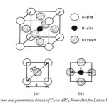
Many oxide structures are based on close packing of cations and anions. A somewhat different structure occurs where large cations are present, which can form a close packed structure along with the oxygen ions. Calcium titanate (CaTiO3) is the first compound to be classified as a Perovskite invented by Russian geologist Perovsky. The commonly studied ferroelectrics have the cubic Perovskite structure (in paraelectric phase) with chemical formula ABO3. For convenience, the structure drawn in Fig.1 as A-site cations occupying the corners of a cube, and B-site cations on the body center. Three oxygen atoms per unit cell are on the faces. The lattice constant of these Perovskite is always close to 4a (where ‘a’ is the lattice constant). Because, the rigidity of oxygen octahedral network and well defined oxygen ionic are having radii of 1.350 Å. The A-site cation has 12- and B-site cation has 6- coordinates. The site-A cation is generally bigger than the site-B cation. The oxygen anion has 6 as the coordination number. All the ions assumed as hard spheres, and the lattice parameter ‘a’ of the cubic Perovskite is given by
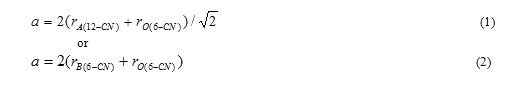
as shown in Fig. 1 (a) and (b). Here, rA(12-CN), rB (6-CN) , and rO(6-CN) are the ionic radii of the 12-coordinated site-A cation, 6-coordinated site-B cation, and 6 – coordinated oxygen anion respectively. The stability of the Perovskite structure can be described geometrically as the ratio of Eq. (1) to Eq. (2), called as the tolerance factor – ‘t’. It is given by
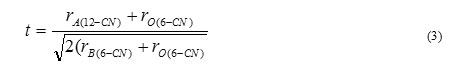
It is advantageous if the A- and B-site cations are in contact with oxygen anions for an ABO3 compound for forming a steady Perovskite structure. Thus, if the tolerance factor t »1.0, then the Perovskite structure is more stable. An advantage of the Perovskite structure is that different cations could be substituted on both A and B site without any drastic change in the overall structure. Complete solid solution is easily formed between many cations, often across the entire range of composition. Simple solid solutions are basically of two types: substitutional solid solutions and interstitial solid solutions. In substitutional solid solutions, the atom that is being introduced directly replaces an atom of the same charge in the parent structure. In case of interstitial solid solutions, the introduced species occupies a site that is normally empty in the crystal structure. Even though two cations are compatible in the solution, their individual behavior can be radically different when apart. Thus, it is possible to change the properties of the materials like Curie temperature, piezoelectric coefficient etc. with a small substitution of given cation.
Ferroelectric and Magnetic Materials
Magnetic and Ferroelectric materials are the customary subjects of research area and have been leading the most significant technological advances in these days. These materials have several applications in modern technology. For example, the consumers’ electronic products are generating huge data and are stored as regions of opposite magnetic polarization in ferromagnets. The sensors industry depends mostly on ferroelectrics materials. Many ferroelectric materials are also ferroelectric – i.e., A change in their electric polarization is accompanied by a change in shape. Consequently, they are used to convert sound waves into electrical signals in sonar detectors. In actuators they convert electrical impulses into motion. Ferro-electricity and Magnetism are concerned with off centre structural distortions of the material and local twists. These two apparently unrelated phenomena may coexist in certain odd materials. These materials are known as multiferroics [2-14]. The word “electromagnetism” derives from the fact that the magnetic and electric fields are interdependent. A changing magnetic field produces an electric field, whereas an electric current, produces a magnetic field (Biot-Savart law). Electromagnets are coiled wire or loops, which are bulky and difficult to fabricate. The magneto-electric effect in a solid i.e., the induction of magnetization by means of an electric field and the induction of an electric polarization (P) by magnetic field are observed by Pierre Curie [15]. He studied the analogy of the electromagnetic phenomena in solids and in vacuum. This analogy is significant from the standpoint of applications. The efficient control of magnetism by an electric field in a solid could help the technology of spintronics used for magnetic random access memory and magnetic storage.
Ferroelectricity
Ferroelectrics are the materials that have two or more equilibrium orientations of impulsive polarization vector in the absence of an external electric field. The spontaneous polarization vector may be switched between these two orientations by an electric field [16]. Two main types of a ferroelectric behavior can be distinguished – displacive and order-disorder. The displacive type behavior is due to an ion getting displaced from the equilibrium position. Hence it acquires a permanent dipole moment. At high temperatures (T > TC, where TC is a ferroelectric Curie temperature), the thermal energy is sufficient to allow the ions to move randomly from one position to another, so there is no fixed asymmetry. When the temperature is below TC, the ion is frozen in an off-center position. This gives a net dipole moment. In an order-disorder ferroelectric, a dipole exists in each unit cell. But at high temperatures, they are pointing in random directions. When the temperature is lowered, the dipoles get arranged in order and become aligned in the same direction within a single domain.
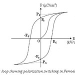
Ferroelectric polarization hysteresis loop shown in (Fig.2) is the characteristic of ferroelectric material, which arises due to the presence of ferroelectric domains in the crystal. Application of an external DC electric field, E >EC (where EC-coercive field) to a polydomain ferroelectric crystal, causes the polarization. The vectors P, having different orientations in different domains, to align themselves parallel to the field direction via the domain wall movement. The minimum value of the DC field, required to move the domain walls, is a measure of the coercive field. The initial value of the vector PS in a polydomain crystal increases with increasing DC field to a maximum value which is a characteristic of the material. Reversing the electric field reintroduces movement of domain walls. This results in the vector PS in different regions to be reversed. At zero current fields, the crystal will have a remnant polarization, which is smaller than the spontaneous polarization. At fully reversed field, the final Ps will have the same magnitude as the original Ps but with opposite sign. The hysteresis loop is a function of the work required to displace the domain walls, which is closely related to the defect distribution in the crystal and to the energy barrier separating the different orientations.
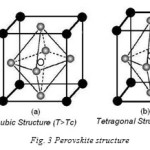
According to their symmetry, crystals can be divided into the 32 point groups with 11 of them being centrosymmetric (non-polar) and 21 lacking an inversion center (polar). Lack of inversion center is a pre-requisite for the piezoelectric behavior of the crystal. The crystal lacking a centre of symmetry will have a net 6 displacement of the negative and positive ions with respect to each other resulting in an electric dipole. For the centrosymmetric crystals, the centers of the two opposite charges will always coincide, so that there is no electric dipole generated. Out of the twenty piezoelectric classes, only ten, possessing a unique polar axis which can be spontaneously polarized, belong to ferroelectrics. Among all the ferroelectric materials, which are studied the Perovskite ferroelectrics are the most extensively and widely used. A perfect Perovskite structure has a general formula of ABO3, where A represents a divalent or trivalent cat-ion, and B is a tetravalent or trivalent cation. The origin of ferroelectricity in this class of materials can be explained using the well-known example of BaTiO3. BaTiO3 is a ferroelectric material with a Perovskite structure as shown in Fig.3. It is the first discovered piezoelectric ceramic [17].
BaTiO3 has a cubic structure above Curie temperature Tc, 120ºC. Cubic BaTiO3 is nonferroelectric because, the centers of negative and positive charges overlap as the ions are symmetrically prearranged in the unit cell. It has tetragonal structure below TC, in which the O-2 ions in the BaTiO3 crystal are shifted in the negative C-direction, while the Ti+4 ions are shifted in the positive C-direction. It results in an electric dipole along the C-axis. Therefore BaTiO3 is ferroelectric in tetragonal structure. The behavior of the spontaneous polarization of ferroelectrics can be explained by thermodynamic (Landau-Ginzburg-Devonshire) theory [16, 18]. In the basic Landau-Ginzburg-Devonshire theory, one assumes that the free energy may be expanded in a power series of the order parameters of the system. For a ferroelectric, the macroscopic order parameter is polarization P:

Where the coefficients αn are temperature dependent. This series does not contain terms in odd powers of P if the un-polarized crystal has a center of inversion symmetry. The value of P in thermal equilibrium is given by the minimum value of F as a function of P; differentiating the equation above with respect to P gives:

The coefficient α1 takes the form α1 = γ (T − T0), where γ is a positive constant and T0 may be equal to or lower than the phase transition temperature, TC. The assumed form of α1 is a necessary result of mean field theory and its validity is supported by the experimentally observed Curie-Weiss law. A small positive value of α1 indicates that the lattice is “soft” and close to instability. A negative value of α1 indicates that the un-polarized state is unstable.
When α2 is positive, we can neglect the α3 term. The polarization for zero fields can be found from Eq.6.
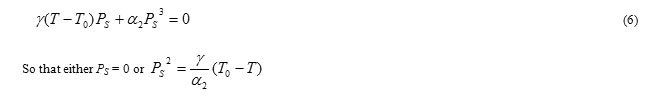
For, T ≥ T0, PS = 0 since γ and α2 are positive. Therefore, T0 is the Curie temperature. For T< T0, the minimum of the free energy in zero field is at

Which is plotted in Fig.4(a). Changes in the free energy and polarization at the transition temperature are continuous and it is a second order transition. When α2 is negative, the transition is of first order. We must retain α3 and take a positive value to ensure that F converges. The equilibrium condition for E = 0 in this case is:
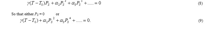
At the transition temperature TC, the free energies of the paraelectric and ferroelectric phases are equal. The existence of meta-stable phases during the phase transition is characteristic of first order transitions. Correspondingly, a sudden jump in polarization occurs at TC as shown in Fig. 2.3 (b). In the present study an attempt is made for the synthesis and characterizations of BiFeO3 and BiFeO3 with CrFeO4 for different percent compositions discussed in chapters 4 and 5 respectively.
 |
Fig4: Polarization vs. temperature plot for (a) second order and (b) first order phase transitions.
Click here to View figure
|
Multiferroic Materials & Magneto-Electric Effect
As per definition, a single-phase Multiferroic [5] material is one, which consists of 2 or all 3 of the ‘ferroic’ properties: i.e., ferroelectricity, ferroelasticity and ferromagnetism. On the other hand, the current tendency is to eliminate the requirement of ferroelasticity, but to include the possibility of ferrotoroidic order. Furthermore, the classification of a Multiferroic is widening to include antiferroic order. The magneto-electric effect is defined as the induction of polarization by means of a magnetic field and induction of magnetization by an electric field. Magneto-electric coupling may exists, whatever be the nature of magnetic and electrical order parameters. For example this occurs in paramagnetic ferroelectrics [14]. Magneto-electric coupling may occur directly between the two order parameters, or indirectly via strain. The nontrivial spin-lattice coupling in these multiferroics has been manifested through various forms, like linear and bilinear magneto-electric effects [19, 20], polarization change through field-induced phase transition [21, 22], magneto-dielectric effect [8, 10], and dielectric anomalies at magnetic transition temperatures [11, 12].
Magnetoelectric multiferroics have all the potential applications of both their parent ferroelectric and ferromagnetic materials [23]. Specific applications, that have been proposed for such materials include multiple-state memory elements, magnetic field sensors, electric-field-controlled ferromagnetic resonance devices, and transducers with magnetically modulated piezoelectricity. The ability to couple with either the magnetic or the electric polarization offers an extra degree of freedom in the design of conventional devices. It was initially proposed that both magnetization and polarization could independently encode information in a single multi-ferroic bit. Four-state memory has recently been demonstrated [24], but in practice, it is likely that the two order parameters are coupled [20, 9]. Coupling could permit data to be written electrically and read magnetically. This is attractive, since it would use the best aspects of magnetic data storage and FeRAM.
In the early 1894, Curie [15] claimed that symmetry conditions enable the bodies containing asymmetric molecules to be polarized in a magnetic field and, magnetized in an electric field. The existence of magneto-electric materials was first experimentally observed in an un-oriented Cr2O3 crystal by Astrov in 1960 [25]. Rado and Folen then revealed the anisotropic nature of the magneto-electric effect in oriented Cr2O3 crystals [26, 27]. Smolensky et al [28] experimentally proved the existence of magneto-electric effect in a solid solution of PbFe2/3W1/3O3-Pb2MgWO6. Zhdanov et al. independently confirmed the existence of magneto-electric Perovskite materials based on a study on the PbTiO3-BiFeO3 and BiFeO3 [29-31] systems. Later, a magneto-electric effect was revealed in other structures and more and more systematic studies were undertaken [7, 34, 32].
BiFeO3, with its magnetic and electrical properties has created interest as the material with many applications. It was expected to form a new type memory by the combination of ferromagnetic and ferroelectric properties. Tabares-Munoz et al[33], observed the ferroelectric/ferroelastic single domain using polarized light microscopy. After this observation, the controversy surrounding the ferroelectric nature in BiFeO3 was solved. BiFeO3 is reported to exhibit about a weak ferromagnetic ordering and eight structural transitions [34, 35]. The neutron diffraction studies are conducted at room temperature. This revealed that BiFeO3 has compensated anti-ferromagnetic ordering (TN ~397°C) with a cycloidal spin arrangement, which is disproportionate with its lattice[36]. In BiFeO3, the ferroelectric phase is stable up to 836°C. It is very difficult to observe ferroelectric loop at room temperature because of the low resistivity of the sample. The measurements are done at 80KV by Teague et al[37], to enhance the resistivity and observe a hysteresis loop. They obtained a loop on a single crystal, with a spontaneous polarization of 3.5 mC/cm2 in the (100) direction. The existence of Bi2Fe4O9 as an additional impurity phase in spite of adopting the improvised method suggested by Sosnowska et al[37] and Achenbach et al[38] is represented by several investigations. Synthesis by microwave-hydrothermal technique is reported to give rise to pure binary oxide[39]. Forming a solid solution of BiFeO3 with other ABO3 type of Perovskite helps to reduce the impurity and enhances the resistivity [40, 41]. This enables the study of physical properties of BiFeO3 rich phases and extrapolation of the data to the pure compound. In present work, an attempt is made to study the effect of sintering temperature on electrical and structural properties of BiFeO3 ceramics, prepared using sol-gel technique.
CrFe2O4 – BiFeO3 Perovskite Multiferroic Materials
It is emphasized that the Multiferroics are a rare class of materials, since ferroelectricity and ferromagnetism make them an exclusive group. Presently, they are a hot research area in view of the many novel applications. Equilibrium contributions of the two phases like ferrite and ferroelectric form magneto-electric composites. These materials are used in sensors, transducers, switching devices and data storage [42]. In addition to the potential application as magneto-electric devices, they are likely to find applications as microwave absorption materials also due to magneto-electric coupling [43]. Perovskite-type BiFeO3 is one of the multiferroics with both ferroelectric (Tc=1103K) and G-Type anti-ferromagnetic (TN =643 K) nature [44-47]. In BiFeO3, Bi-O orbital hybridization due to Bi 6s2 lone pair is responsible for the ferroelectric instability, while Fe-O-Fe anti-symmetric Dzyaloshinskii-Moriya exchange gives rise to a complicated magnetic order [48]. The low resistivity of the BiFeO3 ceramics is mainly caused by existence of Fe2+ and oxygen deficiency [49]. The selection of ferrite and ferroelectric materials depends on factors like high magnetostriction coefficient, piezoelectric coefficient, high dielectric permeability and poling strength. CrFe2O4 is an IIB-type half-metal material. Its molecular magnetic moments are about 5.6μB which is higher than that of Fe3O4, 4.0μB [50].
From a theoretical study of cat-ion distribution of CrFe2O4, it is observed that it has Fe3+ at tetrahedral site, Fe2+ and Cr3+ at octahedral site [51]. Till now, scholars have synthesized nanocomposites of ferrites (CuFe2O4, CoFe2O4 and ZnFe2O4) with PZT/BaTiO3/BiFeO3 both in bulk and thin filmsin order to enhance the Multiferroic properties [52-54]. An important property is the coupling between electrical and magnetic dipole. The coupling can be induced by magneto-electric effect. Understanding the coupling between the magnetic and dielectric properties of nanocomposites is a hot area of research. The ultimate goal of controlling the magnetic/dielectric state using electrical/magnetic field requires that both these properties are coupled. The magneto-electric couplings of most of the materials are normally weak at room temperature. Hence, it is difficult to find a material with a large magneto-electric effect at room temperature. To find out the materials which have large magneto-electric effect at room temperature a lot of research is started now [55, 56]. Very few papers have been reported on CrFe2O4 -BiFeO3 spinel-perovskite nanocomposite. Therefore in the present a systematic study is carried out on structural, dielectric, magnetic and magneto-electric properties of nanocomposites xCrFe2O4-(1-x) BiFeO3 with x = 0.0, 0.1, 0.2, 0.3 and 0.4 synthesized by sol gel technique.
Experimental Procedure
As discussed in the above sections, the properties of BiFeO3 phases are studies and extrapolated to set the properties of the pure compound. An attempt is made to estimate the effect of sintering temperature on electrical and structural properties of BiFeO3 ceramics prepared using sol-gel technique by Ratnakar Pandu et al [57]. In their experiment, BiFeO3 is made by sol-gel technique. All reagents are in the analytical grade. Fe(NO3).9H2O, Bi(NO3).5H2O, citric acid and ethylene glycol are used as starting materials. In the first step, in the distilled water, an aqueous solution of citric acid is made. Then bismuth and ferric nitrates are added to this solution with thoroughly mixing at 60-700C. This is mention to get a homogeneous mixture and to avoid precipitation. Thus a brown color citrate mixture is obtained with clear solution and without precipitation. Then the citric acid/ethylene glycol in the ratio of 60:40 is added to the solution. Subsequently the solution is heated at 6000C for 5 hours. Initially this solution was started to swell and filled the beaker by producing a foamy precursor. This foam contains light and homogeneous flakes of tiny particles. The formation of BiFeO3 is checked by XRD technique with Cu Ka radiation (l=0.15418 nm), using a BRUKER D8 XRD spectroscope. The surface grain distribution and composition analysis of BiFeO3 samples were studied using Field Emission Scanning electron micrographs (FESEM), Quanta 200 attached with Energy dispersion X-ray spectrometer (EDAX). Thermo-gravimetric (TG) and differential thermal gravimetric analysis are conducted and checked the stability and phase transformation in the samples. To study ferroelectric hysteresis behavior, a modified Sawyer–Tower circuit is used.
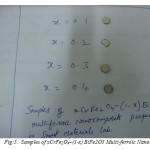
Similarly, Spinel-perovskite nano-composites of xCrFe2O4-(1-x) BiFeO3 with x values taken as 0.0, 0.1, 0.2, 0.3 and 0.4 are synthesized by sol-gel process (synthesized samples are shown in Fig.5). All reagents are taken on the basis of analytical grade, Fe (NO3).9H2O, Bi(NO3).5H2O and Cr(NO3).9H2O, ethylene glycol and citric acid are used as starting materials. Suitable molar metal nitrates are fixed at the proportions of Cr: Fe: Bi, ratios of 1:11:9, 2:12:8, 3:13:7, 4:14:6 for x values 0.1, 0.2, 0.3, and 0.4 respectively. Hydraulic press, Weighing balance and hot air oven are used for preparation of these samples. An aqueous solution of citric acid is made in the distilled water. Then chromium nitrate, bismuth nitrate and ferric nitrate are added to this solution by continuous stirring at 60-700C. This keeps with no precipitation and obtained a homogeneous mixture. A clear solution of brown color of the citrate mixture thus obtained without precipitation. Then ethylene glycol is added to this solution, with ethylene glycol/ citric acid in the ratio of 40:60. On complete evaporation of water by heating the solution on a hot plate, a gel is formed. Then the gel is decomposed at different temperatures in the range of 4000C – 7000C. The gel initially started to swell and filled the beaker producing a foamy precursor consisting of very light and homogeneous flakes of very small particle size. Structural characterization and particle morphology study of the synthesized powder is conducted using XRD by monochromatic Cu Kα radiation and TEM respectively. The dielectric measurements are carried out on silver coated pellets using HIKOI-3532 LCR Hi-Tester. Magnetic measurements are carried out at room temperature using a VSM (vibrating sample magnetometer) with a maximum magnetic field of 5kOe. Variations of dielectric constant as a function of magnetic field are also studied.
Results and Discussions of Bifeo3 Nanoceramics
BiFeO3 is the rhombohedrally indistinct perovskite material. This is belong to the space class R3c, with rhombohedral lattice parameters aR =5.63 Å and αR =59.35°. In other words it has hexagonal parameters ahex = 5.58 Å, chex =13.87 Å [59-61]. Preparation of phase-pure BiFeO3 is difficult because of its narrow temperature range of phase stabilization. Different impurity phases are reported, mainly Bi2Fe4O9, Bi12(Bi0.5Fe0.5)O19.5 and Bi25FeO40, since BiFeO3 is metastable with respect to Bi2Fe4O9 (mullite phase) and Bi25FeO39 (sillenite phase) [62, 63].The presence of these impurities results in leakage current in BiFeO3. It results in poor ferroelectric property and thus causes to be this material is not suitable for practical applications. The available methods, for formation of phase-pure BiFeO3 with improved multi-ferroic properties are (a) forming solid solution of BiFeO3 with other ABO3 type of perovskites like PbTiO3 [64,65] (b) calcinations of stoichiometric mixture of Bi2O3 and Fe2O3 followed by discharging with nitric acid [66] and (c) rapid liquid phase sintering of BiFeO3 [67, 68].
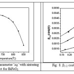 |
Fig7: Variation of Lattice parameter ‘aR’ with sintering temperature plot for BiFeO3
Fig8: b1/2 cosq vs. sinq plot for BiFeO3.
Click here to View figure
|
Selbach et al., on the basis of thermodynamics have suggested that isovalent substitution with a larger cat-ion on the A site or a smaller cation on the B site would increase the stability of BiFeO3 relating to the binary oxides and possibly also relating to the Bi2Fe4O9 mullite and Bi25FeO39 sillenite phase [69, 70]. Substitution of a more acidic cation on the B site or a more basic cation on the A site is also expected to stabilize the perovskite phase. They also reported that La3+ is about the same size as Bi3+, and although the space group changes with high substitution levels, perovskite phase is obtained with up to 40% La3+. Rare earth ions are smaller than Bi3+, but more basic cat-ions, hence the stable solid solutions prepared at ambient pressure have been reported up to 15-20% substitution [71-74]. Fig.6. shows the XRD patterns of BiFeO3,sintered at 650, 700, 750, 800, 825 and 850°C. From the XRD pattern, it is noted that the major peaks of all sintered samples belong to rhombohedrally fuzzy perovskite BiFeO3 (R-phase), although tiny amounts of Bi2O3 were detected due to excessive Bi used for compensating volatilization during synthesis. Moreover, the formation of BFO (R-phase), the formation of the minor impure phases, like Bi46Fe2O72 (non perovskite paramagnetic phase shown by * symbol) was detected from the XRD analysis. BiFeO3 is a metastable composite and because of its chemical kinetics of formation. It is always associated with some impurities which do not contribute for the observed magnetic and dielectric properties, as reported by several research scholars [75, 76]. The phase analysis is carried out by taking into account the hexagonal BFO unit cell. This unit cell of BFO system consist two formula pseudocubic units cells of BiFeO3. The lattice parameters for rhombohedral unit cell of BiFeO3 are calculated from the indexed XRD pattern for BFO samples sintered at 8500C as shown in Fig.6. Using 2q values from the XRD graph and (hkl) values from the standard JCPD- 86-1518 card the lattice parameters for the unit cell are generated. The calculated values of the lattice parameters for the hexagonal unit cell of BiFeO3 matched well with the values reported in the literature [60, 61] which is in the range of which is in the range of 5.5575 – 13.861 Å.
The variation of lattice parameter ‘aR’ with sintering temperature is given in Fig.7. From the plot of lattice parameter, it is found that with increasing sintering temperature the lattice parameter ‘aR’ decreases for BiFeO3. In this research work the Williamson–Hall approach is used for de-convoluting crystallite size and strain contribution to the X-ray line broadening (β1/2) in the present materials since the Scherrer’s formula does not take the strain contribution into account. According to this approach, the X-ray line broadening is a sum of the contribution from small crystallite size and the broadening caused by the lattice strain present in the material [77], i.e.
β1/2 = βsize + βstrain (10)
where βsize = l/Lcosq (from Scherrer’s formula) and βstrain = 4h tanq; where h is strain
Therefore Eq.10 becomes β1/2 = l/L cosq + 4h tanq (11)
β1/2 cosq/l = 1/L + T sinq/l, where T = 4h, is a measure of strain present in the lattice. Hence by plotting β1/2 cosq vs. sinq, it is found that the crystallite size from the intercept of the line at x = 0. The lattice strain and crystallite size is calculated from Fig.8. using the above explained expression (eq.11) for BiFeO3 sintered at different temperatures. The variation of crystallite size and strain with different temperature are plotted in Fig.9. (a) and (b) respectively.
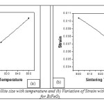 |
Fig9: (a) variation of Crystallite size with temperature and (b) Variation of Strain with sintering temperature plot for BiFeO3.
Click here to View figure
|
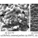
From the plot of crystallite size verses sintering temperature, it is found that with increasing sintering temperature crystallite size increases and strain decreases. Fig.10. shows the FESEM micrographs of BiFeO3 sintered at different temperature. The microstructures of the sintered BiFeO3 pellets specified spherical grains, which are uniformly and homogeneously distributed. These microstructures also reveal that the sintered pellets are reasonably dense. Also, it was found that the edges of the grains are not sharp, which shows melting like behavior resembling liquid phase sintering.
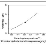
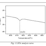
The Fig.11 is shown the variation of grain size with sintering temperature. Grain size measurement is complicated by a number of factors. First, the three-dimensional size of the grains is not constant and the sectioning plane will cut through the grains at random. Thus, on a cross-section it is observed a range of sizes, none larger than the cross section of the largest grain sampled. Grain shape also varies, particularly as a function of grain size. So the intercept approach is applied for measuring grain size. In this method, one or more lines are superimposed over the structure at a known magnification. The true line length is divided by the number of grains intercepted by the line. This gives the average length of the line within the intercepted grains. This average intercept length will be less than the average grain diameter but the two are interrelated. Grain size was observed to increase with increase in sintering temperature. This happens because as the sintering process continues at higher temperatures, the individual powder particles lose their identity completely and grain boundaries move across prior particle boundaries. Larger grains replace the original fine particle structure which influences the dielectric and electrical properties of the samples. In order to observe the phase transition temperature, the DTA curve of BFO is shown in Fig.12. Ferroelectric to paraelectric transition temperature (Tc) was detected by DTA analysis, which shows that the Curie temperature of pure BiFeO3 is 814°C which is very close to the ideal value (827°C) found by dielectric measurement [78].
Results and Discussions of Nanocomposites of x CrFe2O4 – (1-x) BiFeO3
Fig: 13(a) shows XRD pattern of nanocomposites of xCrFe2O4 – (1-x) BiFeO3 with x= 0.1, 0.2, 0.3, 0.4 (samples in Fig.5) powder annealed at 7000C for two hours. At 7000C possible peaks of BiFeO3 and CrFe2O4 have been formed. All the peaks positions are well matched in the XRD pattern of CrFe2O4 and BiFeO3 which able to be identify to appear from the spinel structure of the CrFe2O4 and BiFeO3 presenting that the samples are formed in pure composite phase. Fig: 13-b shows that peaks are shifted to lower Bragg angles as concentration of CrFe2O4 is increased indicating lattice distortion.
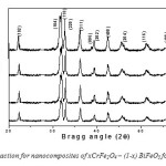 |
Fig13: (a) X-ray diffraction for nanocomposites of xCrFe2O4 – (1-x) BiFeO3 for x=0.1, 0.2, 0.3 and 0.4
Click here to View figure
|
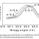 |
Fig14(b): XRD patterns for nanocomposites of xCrFe2O4–(1-x) BiFeO3 for x=0.10, 0.20, 0.30, 0.40. Showing peak shift as concentration of CrFe2O4 is increased indicating lattice distortion.
Click here to View figure
|
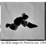
pattern, which are the reflections of the spinel phase of (CrFe2O4) and Perovskite phase (BiFeO3). The diffuse diffraction spots confirm the nano-size of the synthesized material. Variation of magnetization of nanocomposite as a function of CrFe2O4 is shown in Fig: 16.The increase of CrFe2O4 concentration in nanocomposites shows the increase in magnetization which has also been reported for CoFe2O4-BiFeO3 nanocomposites [171].
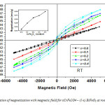 |
Fig16: Variation of magnetization with magnetic field for xCrFe2O4– (1-x) BiFeO3 at room temperature.
Click here to View figure
|
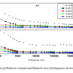
Fig: 17 shows variation of dielectric constant (ε) and dielectric loss (tanδ) with frequency for the nanocomposites xCrFe2O4-(1-x) BiFeO3 with x=0.00, 0.10, 0.20, 0.30 and 0.40. Due to Maxwell-Wagner [80, 81] type interfacial polarization the low value of the dielectric constant at high frequency and the high value of dielectric constant at low frequency indicate large dielectric dispersion. This is in agreement with Koops phenomenological theory [82]. The high values of dielectric constant at lower frequencies may be explained on the basis of space charge polarization due to inhomogeneites present in dielectric structure viz. porosity in the nanocomposite system. Decrement of dielectric constant for nanocomposites with x=0.10, 0.20, 0.30 and 0.40 may be accepted on the basis of Ginzburg-Landau theory. This explains the origin of anomaly in dielectric constant (ε) on the magnetic order of ferroelectromagnets with TM << TE. The difference of the dielectric constant (δε) below temperature TM will be proportional to square of the magnetic order parameter i.e., δε ~ γM2, where M is magnetization. The sign of δε depends on the sign of the constant magneto-electric interaction (γ). It can be either positive or negative [83].
The dielectric constant variation (Fig: 18(a)) with the applied external magnetic field (0-9kOe) is found to be above 0.05% for x=0.2, 0.3, which is high compared to other reported values [84]. This indicates the presence of coupling effect at room temperature for nanocomposite xCrFe2O4-(1-x) BiFeO3, which might have been induced by magneto-electric coupling. Magneto-capacitance is found to decrease at higher field for x=0.2 and 0.3. It is low for x=0.4 compared with x=0.2 and x=0.3. The change of the dielectric constant (ε) under the variation of magnetic field can be induced by magneto-electric coupling effect as well as other factors such as magnetostriction effect. This occurs due to the change in lattice parameters on applying magnetic field. The change in the sample dimension by the magnetic order, i.e., magnetostriction, might be considered as the origin of the observed magneto-capacitance. This factor may be considered for x=0.4. Also, It has been reported that the magnetic domain rotation least affects the dielectric constant at low temperature [85].
Fig: 18(b) and (c) illustrates the temperature dependence of dielectric loss and dielectric constant at 1 kHz frequency for nanocomposites respectively. One broad peak (↑) is observed at around 1800C for x=0.4 nanocomposite. This peak is shifted to lower temperature as concentration of CrFe2O4 increased. This peak shift may be ascribed to structure distortion due to ferrite phase. This peak could be one of the six transitions reported by Khijch et al [86] and Pajak et al [87]. BiFeO3 has the transition at TN = 3970C. This is not clearly evident in the Fig: 18(b) because of the high dielectric loss in the samples. These losses could be due the conducting behavior of the nanocomposites at higher temperatures, possibly due to the thermally activated conductivity. In BiFeO3, oxygen deficiency is an inherent problem. Hence space charge polarization is always present. However, due to the thermally activated process, there is considerable increase in space charge polarization and material conductivity at higher temperature [88]. Hence, the peak at 3970C is not clearly marked in the nanocomposites with x=0.1, 0.2, 0.3 and 0.4.
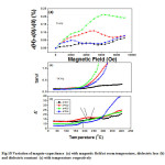 |
Fig18: Variation of magnto-capacitance (a) with magnetic field at room temperature, dielectric loss (b) and dielectric constant (c) with temperature respectively
Click here to View figure
|
Conclusions and Scope of Future Work
The following conclusions are drawn from the present research work.
- Synthesis of BiFeO3 is carried out at low temperature using sol-gel method.
- From the X-ray Diffraction pattern it is seen that
i) The crystallite size increases with increase in sintering temperature.
ii) The strain in the crystallite decreases with increase in sintering temperature.
iii) The crystallite size increases with increasing temperature the lattice parameter decreases.
3. From an SEM micrograph, it is shown that the samples are homogeneous and that the grain size increases with increasing sintering temperature and the particle size follows the Gaussian distribution.
4. The DTA analysis shows that the Curie temperature of pure BiFeO3 is 814°C which is closer to that of ideal temperature 827°C.
5. In the experiment xCrFe2O4-(1-x) BiFeO3 with x = 0.0, 0.1, 0.2, 0.3 and 0.4, the XRD and thermal analysis confirmed that at 7000C the phase was formed. The particle size observed in TEM is about ~100nm.
6. The change of dielectric loss and dielectric constant with frequency confirmed distribution in the range of low frequency.
7. The Magnetization is estimated and observed the ferrite concentration and annealing temperature. Dielectric analysis confirms the conducting behavior at high temperatures.
8. Magneto-capacitance is estimated in the prepared nano-composites. This approves the presence of magneto-electric coupling in the synthesized nano-composites at room temperature.
Scope for the Future Work
The research work reported in this paper mainly deals with the preparation by an economical methods and characterizations of some BiFeO3, CeFe2O3-BiFeO3 nanocomposites and Carbon Nanotubes. Multiferroics are the potential keystones in upcoming magnetic data storage and spintronics devices provided a simple and fast way can be found to turn their electric and magnetic properties on and off. The present experimental study on synthesis and characterizations of xCrFe2 O4-(1-x) BiFeO3 Multiferroic nanocomposites, with x = 0.0, 0.1, 0.2, 0.3 and 0.4 can be used as reference work and be extended for further studies with different ‘x’ values for different properties. Further, this work can be extended to study the carbon nanotubes may be reinforced into BiFeO3 nanoceramics and convert to metallically conductive composites. By using spark-plasma-sintering method [89], we can fabricate nanocrystalline BiFeO3 matrices that retain the integrity of SWCNT in the matrix. The conductivity of these composites increases with increasing content of CNTs.
References
- K. J. Klabunde (Ed.), Nanoscale Materials in Chemistry, Wiley-Interscience, NY, 2001.
CrossRef
- P.J.F. Harris, “Carbon Nanotubes and related structures”, Cambridge University Press, 1999.
CrossRef
- Smolenski G A & Chupis I E, “Ferroelectromagnets”, Usp. Fiz. Nauk, 137, 415, 1982; sov. Phys. Usp., 25, 475, 1982.
CrossRef
- Schmid H, “Multi-ferroic magnetoelectrics”, Ferroelectrics, 162, 317, 1994.
CrossRef
- Wang J et al, “Epitaxial BiFeO3 multiferroics thin film heterostructures”, Science 299, pp1719, 2003.
CrossRef
- Smolensky G A, Yudin V M, Sher E S & Stolypin Yu E, “Antiferromagnetic properties of some Perovskite”, Sov. Phys. JETP, 16, 622, 1963.
- Kimura, T. et al. “Magnetocapacitance effect in Multiferroic BiMnO3” Phys. Rev. B, 67, pp180401, 2003.
- Ascher E, Rieder H, Schmid H & Stösse H, “Some properties of ferromagnetoelectric nickel-iodine boracite, Ni3B7O13I”, J. Appl. Phys., 37, pp1404, 1966.
- Baturov L N et al, “Nonlinear magnetoelectrics and dielectric properties of Ni-I boracite”, Fiz. Tverd. Tela, 20, 2254, Sov. Phys. Solid State, 20, 1300, 1978.
- Scott J F, “Phase transitions in BaMnF4”, Rep. Prog. Phys., 12, pp1056, 1979.
CrossRef
- Katsufuji T, et al “Dielectric and magnetic anomalies and spin frustration in hexagonal RMnO3 (R = Y, Yb, and Lu)”, Phys. Rev. B, 64, pp104419, 2001.
- Fiebig M, Lottermoser Th, Fröhlich D, Goltsev A V & Pisarev R V, “Observation of coupled magnetic and electric domains”, Nature, 419, 818, 2002.
CrossRef
- Ponomarev B K, Ivanov S A, Popov Yu F, Negrii V D & Red’ kin B S, “Magnetoelectric properties of some rare earth molybdates”, Ferroelectrics, 161, 43, 1994.
CrossRef
- Curie P, “Sur la symétrie dans les phénomènes physiques, symétrie d’un champ électrique et d’un champ magnétique”, J. Phys., 3 (Ser. III), 393, 1894.
- Lines M E & Glass A M, “Principles and applications of ferroelectrics and related materials”, Clarendon Press Oxford, 1977.
- Berlincourt D, “Piezoelectric ceramics: characteristics and applications”, J. Acoust. Soc. Am., 70(6), 1586, 1981.
CrossRef
- Kittel C, “Introduction to Solid State Physics”, 1976.
- Rivera J P, “On definitions, units, measurements, tensor forms of the linear Magnetoelectric effect and on a new dynamic method applied to Cr-Cl boracite”, Ferroelectrics, 161, 165, 1994.
CrossRef
- Schmid H, “On a Magnetoelectric classification of materials”, Int. J. Magn., 4, pp337, 1973.
- Popov Yu. F. et al, “Low-temperature phase transition in EuMn2O5”, Physica B, 1402, pp284–288, 2000.
- Popov Yu. F. et al, “Features of the magnetoelectrics properties of BiFeO3 in high magnetic fields”, J. Low-Temp. Phys., 27, pp478, 2001.
CrossRef
- Wood V E & Austin A E, “Magnetoelectric Interaction Phenomena in Crystals”, Freeman A J, Schmid H, Eds., Gordon and Breach: Newark, NJ, 1975.
- Gajek, M. et al. “Multiferroic tunnel junctions”, Preprint at khttp:// arxiv.org/cond-mat/0606444l, 2006.
- D. N. Astrov, “The Magnetoelectric effect in Antiferromagnetic”, J. Exptl. Theory Phys. (USSR) 38, 984 , 1960. [Sov. Phys. JETP 11, 708, 1960)].
- V. J. Folen, G. T. Rado & E. W. Stalder, “Anisotropy of the Magnetoelectric Effect in Cr2O3”, Phys. Rev. Lett. 6, pp607, 1961.
CrossRef
- G. T. Rado & V. J. Folen, “Observation of the Magnetically Induced Magnetoelectric Effect and Evidence for Antiferromagnetic Domains”, Phys. Rev. Lett., 7, pp310, 1961.
CrossRef
- SmolenskyGA, IsupovVA, Krainik NN& Agranovskaya AI, Izv.AN SSSR. Ser.Phys.,vol.25,pp1333, 1991.
- Fedulov SA, Venevtsev Y N, Zhdanov G S, Smazhevskaya E G, & Rez I S, Kristallografiya, 7, pp77, 1962.
- S. V. Kiselev, R. P. Ozerov & G. S. Zhdanov, Dokl. AN SSSR 145, 1255, 1962.
- Venevtsev Y N, Gagulin V V, & Zhitomir sky I D, “Material science aspects of seignette-magnetism problem”, Ferroelectrics, 73, pp221, 1987.
- Hill N A, “Why are there so few magnetic ferroelectrics”, J. Phys. Chem. B, 104, pp6694, 2000.
- C. Tabares-Munoz et al “Measurement of the Quadratic Magnetoelectric Effect on Single Crystalline BiFeO3”, Jpn. J. Appl. Phys. 24, pp1051, 1985.
- N.N. Krainik, N.P.Khuchua, V.V.Zhdanova, and V. Evseev, J. Phys. C 15, pp4835, 1982.
- M. Polomska, W. Kaczmarek, and Z. Pajak, Phys. Status Solid A 23, 567, 1974.
CrossRef
- I. Sosnowska et al, “Spiral magnetic ordering in bismuth ferrite”, J. Phys. C 15, 1982, pp4835.
- J. R. Teague et al, “Mossbauer Studies BiFeO3-PbTiO3 Perovskite Type Solid Solutions”, Solid State Commun, 8, pp1073, 1970.
CrossRef
- G. D. Achenbach, W. J. James, and R. Gerson, J. Am. Ceram. Soc. 50, 437, 1967.
CrossRef
- S.Komaraneni, V.C.Menon, Q.H. Li, R.Roy, and F.Ainger, J. Am. Ceram. Soc.79, 1409, 1996.
CrossRef
- R. T. Smith, G. D. Achenbach, R. Gerson, and W. J. James, J. Appl. Phys. 39, 70, 1968.
CrossRef
- M. Mahesh Kumar, A. Srinivas, and S. V. Suryanarayana, J. Appl. Phys. 87, 855, 2000.
CrossRef
- M. Fiebig, J. Phys. D.: Appl. Phys. 40, R123, 2005.
CrossRef
- Yu-Qing Kang et al, “Microwave absorption properties of multiferroic BiFeO3 nanoparticles”, Materials Letters. Vol.63 Issue15, 15June 2009, pp1344-1346
- S.T. Zhang et al, “Larger polarization and weak ferromagnetism in quenched BiFeO3 ceramics with a distorted rhombohedral crystal structure”, Applied Physics LettersVol.87, pp262907, 2005.
- Manoj Kumar and K.L. Yadav, “Study of room temperature magnetoelectric coupling in Ti substituted bismuth ferrite system”, J. Applied Physics, Vol.100, pp 07411, 2006.
- Manoj Kumar, K.L.Yadav and G.D. Varma, “Large magnetization and weak polarization in sol-gel derived BiFeO3 ceramics” Materials Letters, Vol.62, pp1159-1161, 2008.
- Poonam Uniyal & K.L. Yadav, ”Study of dielectric, magnetic and ferroelectric properties in Bi1-xGdxFeO3”, Materials Letters Vol.62, pp2858-2861, 2008.
- R. Mazumdar et al, “Ferromagnetism in nanoscale BiFeO3”, Applied Physics Letters Vol.91, pp062510, 2007.
- J.R. Cheng, N. Li, and L.E. Cross, J. Appl. Phy. 94, 5153, 2003.
CrossRef
- LIU Jun et al, “Eletronic Structures of New Half-Metal Material CrFe2O4”, Acta Phy, Chim. Sin. Vol.25(1), pp107-112, 2009.
- K. Nishamol et al, J. Mol, Cata A: Chemical, Vol.209, pp89, 2004.
- Y. Koseoglu, A. Baykal, Muhammet S. Toprak, F. Gozuak, Ali C. Basaran, B. Aktas, J. Alloys Compd Vol.462, pp209, 2008.
- Xian-Ming Liu et al, “Synthesis and magnetic characterization of novel CoFe2O4-BiFeO3 nanocomposites”, Materials Science and Engineering B Vol.121, pp255-260, 2005.
- R.S. Devan, B.K. Chougule, Physica B, Vol.393, pp161, 2007.
- P. Uniyal and K.L.Yadav. “Pr doped bismuth ferrite ceramics with enhanced multiferroic properties”, Journal of Physics: Condensed Matter, Vol.21, pp405901, 2009.
- Manoj Kumar and K.L. Yadav “Magnetoelectric characterization of xNi0.75Co0.25Fe2O4-(1-x)BiFeO3 nanocomposites”, Journal of Physics and Chemistry of Solids Vol.68, pp1791-1795, 2007.
CrossRef
- Moreau, J. M., Michel, C., Gerson, R. & James, W. J. J. “Ferroelectric BiFeO3 X-ray and neutron diffraction study”, Phys. Chem. Solids, 32, 1315, 1971.
CrossRef
- Ratnakar Pandu, K.L Yadav, Amit, P. Ravinder Reddy, AVSSKS Gupta, “Effect of Sintering Temperature on Structural and Electrical Properties of BiFeO3 Multiferroics”, Indian Journal of Engineering and Materials Science, Vol. 17, pp.481-485, 2010.
- Moreau, J. M., Michel, C., Gerson, R. & James, W. J. J. Phys. Chem. Solids, 32, 1315, 1971.
CrossRef
- Kubel, F.& Schmid, H. Acta Crystallogr., Sect. B, 46, 698, 1990.
CrossRef
- Fischer, P., Polomska, M., Sosnowska, I. & Szymanski, M. J. Phys. C: Solid. State Phys., 13, 1931, 1980.
CrossRef
- Morozov M. I, Lomanova N A and Gusarov V V, “Specific features of BiFeO3 formation in a mixture of Bi(III) and iron(III) oxides”, Russ. J. Gen. Chem., vol.73, 1676, 2003.
CrossRef
- Valant M, Axelsson A K and Alford N, “Pecularities of a solid-state synthesis of multiferroic polycrystalline BiFeO3”, Chem. Mater., vol.19, pp5431, 2007.
- Smith R T, Achenbach G D, Gerson R and James W J, “Dielectric properties of solid solutions of BiFeO3 with Pb(Ti, Zr)O3 at high temperature and high frequency”, J. of Applied Physics, vol.39, 1968, pp70.
- Kumar M M, Srinivas A and Suryanarayana S V, “Structure property relations in BiFeO3/BaTiO3 solid solutions”, Journal of Applied Physics, vol.87, pp855, 2000.
- Ghosh S, Das gupta, Sen A and Maiti H S, “Low temperature synthesis of nanosized Bismuth ferrite by soft chemical route”, Journal of American Ceramic Society, vol.88, pp1349, 2005.
- Kumar M and Yadav K L, “Study of room temperature magnetoelectric coupling in Ti substituted bismuth ferrite system”, Journal of Applied Physics, vol.100, pp074111, 2006.
- Wang Y P, Zhou L, Zhang M F, Chen X Y, Liu J M and Liu Z G, “Room-temperature saturated ferroelectric polarization in BiFeO3 ceramics synthesized by rapid liquid phase sintering”, Applied Physics Letters, vol.84, pp1731, 2004.
CrossRef
- Selbach S M, Einarsrud M A and Grande T, “On the Thermodynamic stability of BiFeO3”, Chem. Mater., vol.21, pp169, 2009.
- Selbach S M, Einarsrud M A, Tybell T and Grande T, “Synthesis of BiFeO3 by wet chemical methods”, J. Mer. Cer. Soc., vol.90, pp3430, 2007.
- Yuan G L and Or S W, “Structural transformation and ferroeletromagnetic behavior in single-phase Bi1-xNdxFeO3 multiferroic ceramics”, Applied Physics Letters, vol.89, pp052905, 2006.
- Yan Z, Wang K F, Qu J F, Wang Y, Song Z T and Feng S L, “Processing and properties of Yb-doped BiFeO3 Ceramics”, Applied Physics Letters, vol.91, pp082906, 2007.
- Fanggo C, Guilin S, Kum F, Ping Q and Qijum Z, “Effect of Gadolinium substitution on dielectric properties of Bismuth ferrite”, Journal of Rare Earths, vol.24, pp273, 2009.
- Manoj Kumar and K.L. Yadav, ”Synthesis of nanocrystalline xCuFe2O4-(1-x)BiFeO3 magnetoelectric composite by chemical method”, Materials Letters Vol.61, pp2089-2092, 2007.
- Manoj Kumar & K.L. Yadav, J. Phys. –Cond. Matt. 18, L503-L508, 2006.
CrossRef
- Uniyal P & Yadav KL, J. Appl. Phys., 105, 07D914, 2009.
- Suryanarayana C, Norton MG, In: X-ray diffraction: a practical approach. Plenum Press, New York and London, pp213, 1998.
CrossRef
- Zhao T., Scholl A, Zavaliche F., Lee K, Barry M, Doran A, Cruz M P, Chu Y H, Ederer Spaldin CNA, Das RR, Kim DM, BaekSH, Eom CB &Ramesh R, Nature Materials, 5, 823; doi:10.1038/nmat1731, 2006.
CrossRef
- J.C. Maxwell Electricity and Magnetism. Oxford Univ. Press, London. 1973.
- K.W. Wagner, Ann. Phys. Vol.40, pp818, 1993.
- C.G. Koops, “On the Dispersion of Resistivity and Dielectric Constant of Some Semiconductors at Audio frequencies”, Physics Review, Vol.83, No:1, pp121-124, 1951.
CrossRef
- T. Kimura, S. Kawamoto, I. Yamada, M. Azuma, M. Takno and Y. Tokura, Phys. Rev.B, Vol.67, pp180401, 2003.
- Youn-Ki Jun, kee Hoom Kim and Seong-Hyeon Hong, Solid State Com. Vol.135, pp133, 2005.
- N.N. Kranik, N.P. Khijch, A.A. Bierezhnoi, A.G. Tutov and A.J. Cherkashtscheheo, Izv. Akad. Nauk SSSR, Ser. fiz; 29, pp1026, 1965.
- M. Polomska, W. Kaczmarek and Z. Pajak phys. Stat. sol. (a); 28, pp567, 1974.
- Poonam Uniyal, K.L. Yadav, “Synthesis and study of multiferroic properties of ZnFe2O4-BiFeO3 nanocomposites”, Journal of Alloys and Compunds, Vol.492, pp406-410. doi;10.1016/j.jallcom 2009.10.10275, 2010.
- Chen W X, Tu J P, Wang L Y, Gran H Y, Xu Z D and Zhang X B, “Tribological application of carbon nanotubes in a metal-based composite coating and composites” Carbon 41, 215–22, 2003.
CrossRef
- L.J. Bellamy, “The Infrared Spectra of Complex Molecules”, vol. 1, 3rd ed., Chapman & Hall, 1986.
- P. Chen, X. Wu, J. Lin, K.L. Tan, “High H2 Uptake by Alkali-Doped Carbon Nanotubes under Ambient Pressure and Moderate Temperatures” Science 285, 92, 1999.
CrossRef
- Guo-Dong Zhan, Joshua D. Kuntz, Javier E. Garay, and Amiya K. Mukherjee, “Electrical properties of nanoceramics reinforced with ropes of single-walled carbon nanotubes”, Appl. Phys. Lett. 83, 1228; doi:10.1063/1.1600511, 2003.
CrossRef

This work is licensed under a Creative Commons Attribution 4.0 International License.

![Fig: 6. XRD patterns for BiFeO3 at different sintering temperature [where (*) Bi2O3].](http://www.materialsciencejournal.org/wp-content/uploads/2014/12/Vol11_No2_CrFe2_Ratna_Fig6-150x150.jpg)