Preventing Firing-Induced Curvature of Thin Oxide Pellets - for Ion Irradiation Experiments
Kriti Ranjan Sahu1 and De. Udayan2 
1Physics Dept., ESSB College, Egra 721429, Purba Medinipur,W.Bengal, India,
2Variable Energy Cyclotron Centre, DAE, 1/AF Bidhannagar, Kolkata 700064, India
Corresponding author Email: ude2006@gmail.com
DOI : http://dx.doi.org/10.13005/msri/140203
Article Publishing History
Article Received on : 09 Dec 2017
Article Accepted on : 18 Dec 2017
Article Published : 18 Dec 2017
Plagiarism Check: Yes
Article Metrics
ABSTRACT:
To investigate radiation damage in bulk II-VI oxides with electronic and optical applications, 50 to 55 MeV Li ion beam from the Pelletron at IUAC, New Delhi, is suitable, and has been available. Maximum sample thickness that prevents undesirable ion implantation turns out, from TRIM calculation, to be ~ 200 µm for CdO & ZnO, and 400 to 450 µm for MgO. The need and difficulty of making such ultrathin ceramic samples (as desirable for radiation damage without implantation) are addressed first. Films, easily fulfilling the low thickness requirement, have properties different from the bulk, and are usually on a substrate to complicate the matter. Ultrathin un-fired pellets, in contrast to thick and sturdy pellets, become curved on conventional sintering. Curved pellets are useless for ion irradiation and most other experiments. Qualitative understanding of the curving, its prevention and test of these newly made ultrathin but flat ceramics for swift ion irradiation have been undertaken in this work.
KEYWORDS:
Deformation on sintering; Ion-solid interaction; Sintering deformation-free ultrathin pellets; Radiation damage trials; II-VI semiconductors;
Copy the following to cite this article:
Sahu K. R, Udayan De. Preventing Firing-Induced Curvature of Thin Oxide Pellets - for Ion Irradiation Experiments. Mat.Sci.Res.India;14(2)
|
Copy the following to cite this URL:
Sahu K. R, Udayan De. Preventing Firing-Induced Curvature of Thin Oxide Pellets - for Ion Irradiation Experiments. Mat.Sci.Res.India;14(2). Available from: http://www.materialsciencejournal.org/?p=6587
|
Introduction
II-VI materials often offer better options for electronic and optical applications1 than Si, a group IV semiconductor and workhorse for these applications. Present work focuses on designing radiation damage by a fast ion beam on bulk samples of II-VI oxides CdO, ZnO and MgO. Need, from ion-solid interaction aspect,2 for thin samples and the difficulty of making bulk ceramics with such low thickness are to be addressed first.
Sample thickness (t) should be definitely shorter than the projected range (R) of the ion beam in the sample to avoid ion implantation, if one wants to study pure radiation damage of the sample by the beam – avoiding the property change due to implantation. Thick or thin films, almost always on a substrate, readily offer such thin samples for light or even heavy ions of high energy. But films and bulk materials have usually somewhat different properties. So, radiation damage investigations in films are related to but different from such investigations in the bulk.
Table 1: TRIM calculated Range etc. of O6+ and Li3+ ion beams in different oxides:
O6+ ion beam in ZnO:
|
Energy
(MeV)
|
dE/dx(elec)
MeV/(mg/cm2)
|
dE/dx(nuclear)
MeV/(mg/cm2)
|
Projected range, R
(µm)
|
|
10 MeV
|
5.424
|
0.01044
|
5.78
|
|
100 MeV
|
2.535
|
0.001454
|
65.69
|
Li3+ ion beam in ZnO:
|
Energy
(MeV)
|
dE/dx(elec)
MeV/(mg/cm2)
|
dE/dx(nuclear)
MeV/(mg/cm2)
|
Projected range, R
(µm)
|
|
10 MeV
|
0.982
|
0.00078
|
19.19
|
|
55 MeV
|
0.319
|
0.00017
|
241.2
|
Li3+ ion beam in CdO:
|
Energy
(MeV)
|
dE/dx(elec)
MeV/(mg/cm2)
|
dE/dx(nuclear)
MeV/(mg/cm2)
|
Projected range, R
(µm)
|
|
10 MeV
|
0.802
|
0.00063
|
19.67
|
|
55 MeV
|
0.272
|
0.000145
|
244.64
|
Li3+ ion beam in MgO:
|
Energy
(MeV)
|
dE/dx(elec)
MeV/(mg/cm2)
|
dE/dx(nuclear)
MeV/(mg/cm2)
|
Projected range, R
(µm)
|
|
10 MeV
|
1.392
|
0.000973
|
33.80
|
|
55 MeV
|
0.404
|
0.000215
|
497.5
|
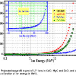
Present goal is to experimentally arrange bulk samples for pure radiation damage by swift ion beams available from accelerators like the Pelletron at IUAC, New Delhi, India (~55 MeV Li3+ beam to get sufficient R), and also to carry out test irradiation runs. Here, R = 245 µm for CdO, 241 µm for ZnO and 498µm for MgO (vide Table 1 and Fig. 1) imply fabrication of pellets of thickness t less than the R values. Such ultrathin pellets generally develop curvature and cracks during sintering (Fig. 2). Using still higher energy to make R > t is not a practical solution. Such higher energies, cause lesser damage and complicate matter by inducing nuclear reactions. The possible alternative of sintering a thick pellet and then thinning it by rubbing the surfaces with fine emery paper proved to be destructive, as the surfaces are usually textured and hence of better quality. With no other options left, present effort has been on discovering a method of sintering flat ultrathin pellets. This paper reports success. As samples, we have chosen MgO (IIa-VIa), ZnO (IIb-VIa) and CdO(IIb-VIa) that are similar compounds. This is a generalized work, not specialized for the IUAC accelerator. However, IUAC Pelletron is one of the highest energy accelerators in India. Still higher energies are not useful in this kind of study, as already discussed. Among various applications of these semiconductors, we note that there are lot of efforts for developing ZnO based p-n junction,3 CdO & CdO-based transparent conductive phases4 etc. There have also been considerable fundamental studies on these three oxides including valence-band density of states investigation5 by XPS and quasi-particle-corrected density-functional theory calculations. All these provide a good base for radiation damage studies.
Table 2: Details of pelletization (using 6 ton-wt.)
|
|
CdO
|
ZnO
|
MgO
|
|
Pellet Dia.(mm)
|
10
|
10
|
10
|
|
Powder Wt. (mg)
|
75
|
77
|
130
|
|
Resulting thickness (µm)
|
210
|
200
|
450
|
Materials and Methods
Ion-Solid Interaction Consideration
Projected ranges (R) of a lightion beam (Li3+ beam) and a heavier ion beam (O6+ beam) in MgO, ZnO and CdO at different ion energies have been calculated (using TRIM programme) in Table 1 to know how thin must the samples be for flawless radiation damage experiments. For example, 100 MeV O6+ ion beam (available at IUAC) has a range of only 65.7 µm in ZnO. Since pellets thinner than 65.7 µm cannot be made by die-&-plunger pressing of powdered sample, O-ion or heavier ion radiation damage on these bulk samples have not been planned in this work. Li3+ beam (with energy = 55 MeV or so) is good, causing more damage than protons and alpha-particles, and having a fairly long range R (Table 1). It appears to be an optimum choice.6 With special care, CdO, ZnO and MgO pellets of 210, 200 and 450 µm could be made by the die-&-plunger method, as will be detailed later. These are thick enough to retain bulk properties, unlike films of thickness less than or comparable to electron (hole) mean free path.
Table 3: (hkl) values, 2θ and spacing d of CdO-800, ZnO-1000 and MgO-200. As calculated from our XRD data using powder-X software.
|
CdO-800
|
ZnO-1000
|
MgO-200
|
|
hkl
|
2θ (°)
|
d(Å)
|
hkl
|
2θ (°)
|
d(Å)
|
hkl
|
2θ (°)
|
d(Å)
|
|
1 1 1
|
33.019
|
2.71124
|
1 0 0
|
31.677
|
2.82238
|
1 1 1
|
36.934
|
2.43180
|
|
2 0 0
|
38.305
|
2.34800
|
0 0 2
|
34.338
|
2.60950
|
2 0 0
|
42.903
|
2.10600
|
|
—
|
43.619
|
2.07337 [12]
|
1 0 1
|
36.152
|
2.48260
|
2 2 0
|
62.297
|
1.48917
|
|
2 2 0
|
55.283
|
1.66029
|
1 0 2
|
47.410
|
1.91604
|
3 1 1
|
74.681
|
1.26997
|
|
3 1 1
|
65.925
|
1.41590
|
1 1 0
|
56.422
|
1.62950
|
2 2 2
|
78.617
|
1.21590
|
|
2 2 2
|
69.297
|
1.35562
|
1 0 3
|
62.684
|
1.48094
|
|
|
4 0 0
|
81.980
|
1.17400
|
2 0 0
|
66.166
|
1.41119
|
|
|
1 1 2
|
67.741
|
1.38215
|
|
|
1 1 2
|
68.177
|
1.37437
|
|
0 0 4
|
72.368
|
1.30475
|
|
|
|
2 0 2
|
76.714
|
1.24130
|
|
|
|
1 1 3
|
80.738
|
1.18927
|
|
|
|
2 0 3
|
89.314
|
1.09595
|
|
|
a = b = c = 4.696Å
|
a = b = 3.2590 Å
and c = 5.2190 Å
|
a = b = c = 4.212Å
|
Table 4: Lattice parameter, a, of CdO-120, CdO-800, MgO-200 and MgO-1000 as a function of Li3+ ion fluence.
|
Dose (Li-ions/cm2)
|
Lattice parameter, a (Å)
|
|
CdO-120
|
CdO-800
|
MgO-200
|
MgO-1000
|
|
5×10¹¹
|
4.69638(21)
|
4.69550(9)
|
4.21141(21)
|
4.21201(06)
|
|
5×10¹²
|
4.69715(33)
|
4.69875(30)
|
4.21085(16)
|
4.21330(18)
|
|
1×10¹³
|
4.69330(18)
|
4.69602(13)
|
4.21065(16)
|
4.21217(13)
|
|
5×10¹³
|
4.69299(20)
|
4.69660(5)
|
4.21165(22)
|
4.21171(16)
|
Literature on thermally induced curving
Curving of materials, including metals, under non-uniform heating is known for a very long time. It is utilized in shipyards, for example, by skilled workers to form curved plates in various shapes under various heating conditions, and theoretical models7 have been attempted. United States Patent 5174068 of 1992 was taken on the “Method and apparatus for preventing thermal damage of work pieces due to heat developed by a grinding process”, a problem very similar to the present one. These related references justify the reality and importance of the problem, also for ultrathin ceramics, for which no publication has been found.
Figure 1: Projected range (R in µm) of Li3+ ions in CdO, MgO and ZnO, and of O6+ ions in ZnO (as a function of ion energy in MeV).
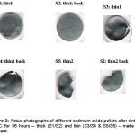
Figure 2: Actual photographs of different cadmium oxide pellets after sintering at 800°C for 36 hours – thick (S1/S2) and thin (S3/S4 & S5/S6) – made without pressure.
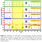
Figure 3: Comparison of XRD peak of (a) un-irradiated CdO-800 (cadmium oxide sintered at 800°C for 36 hours), (b) CdO-800 irradiated with dose 5×10¹¹ ions/cm2 (c) CdO-800 irradiated with dose 5×10¹² ions/cm2 (d) CdO-800 irradiated with dose 1×10¹³ ions/cm2 and (e) CdO-800 irradiated with dose 5×10¹³ ions/cm2.
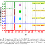
Figure 4: Comparison of XRD peak of (a) CdO-120 (cadmium oxide sintered at 120°C for 36 hours) irradiated with dose 5×10¹¹ ions/cm2 (b) CdO-120 irradiated with dose 5×10¹² ions/cm2 (c) CdO-120 irradiated with dose 1×10¹³ ions/cm2 and (d) CdO-120 irradiated with dose 5×10¹³ ions/cm2.
Sample preparation through special steps
Pellets of 10mm diameter and different thicknesses were made (Table 2) under the same pelletizing load of 6 ton-wt., from Cadmium Oxide (Ma Teck GmbH 99.99+%), Zinc Oxide (Ma Teck GmbH 99.999%), Magnesium Oxide (Ma Teck GmbH 99.99%). Extreme handling care was needed for these delicately thin pellets. These and thicker pellets were heat treated at 800 °C or other temperatures in air for 36 hours8 in a Carbolite Furnace with PID Temperature Controller and then cooled in the furnace with the cooling rate set at 200 °C/h. The 800°C fired sample will be called CdO-800, and so on. Significant electrical conductivity has been reported for Cadmium oxides and Zinc oxides samples.8,9,10
Two types of special firings (Expt.1 & Expt.2, below) were designed to understand and prevent curving of ultra thin pellets during firing.
Expt.1
Fact that only the thin samples got curved or got curvature with multiple depressions and crack/s on firing has been verified by one 800 °C firing of 4 pellets – two thick (~1 mm) and two thin (~200 µm) pellets of CdO.
Expt.2
Hoping to prevent curvature, some pellets have been put under a pressure of 12.1×10⁴ N/m2 during the 800 °C firing, slow cooled after the 36 hour firing and taken out of the furnace at ~ 50 °C. This pressure has been applied by putting ceramic plates of known masses over the pellets of known diameter.
XRD in a Bruker Diffractometer showed the correct phase for each sample for Expt.1 and Expt.2 firings.
Ion Irradiation
More than 10 flat and usable pellets of Cadmium, Zinc and Magnesium Oxides were thus prepared and put on three faces of the all copper IUAC Target Holder (called Ladder). Beam Current for the 50 MeV Li3+ irradiation was never allowed to exceed 3 nA to avoid beam heating of the samples. Aided by a quartz beam viewer, an electro-mechanical device was operated from the Control Room to bring different samples in view of the beam for irradiation. A current integrator measured the charge collected by the sample, with 10 nC denoting one count in the current integrator. This gave the irradiation fluence. XRD in the Bruker Diffractometer have been repeated on the irradiated samples.
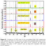
Figure 5: Comparison of XRD peak of (a) un-irradiated ZnO-1000 (zinc oxide sintered at 1000°C for 36 hours), (b) ZnO-125 (zinc oxide sintered at 125°C for 36 hours) irradiated with dose 1×10¹³ ions/cm2 and (c) ZnO-1100 (zinc oxide sintered at 1100°C for 36 hours) irradiated with dose 1×10¹³ ions/cm2.
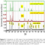
Figure 6: Comparison of XRD peak of (a) un-irradiated MgO-200 (magnesium oxide sintered at 200°C for 36 hours), (b) MgO-200 irradiated with dose 5×10¹¹ ions/cm2 (c) MgO-200 irradiated with dose 5×10¹² ions/cm2 (d) MgO-200 irradiated with dose 1×10¹³ ions/cm2 and (e) MgO-200 irradiated with dose 5×10¹³ ions/cm2.
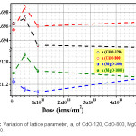
Figure 7: Variation of lattice parameter, a, of CdO-120, CdO-800, MgO-200 and MgO-1000.
Results and Discussion
Expt.1 (above) proved (as shown in Fig. 2) that only ultrathin pellets (~ 200 µm or so, for these materials) got perceptibly curved on firing without an applied pressure. Thick pellets did not bend. The basic finding is that an ultrathin pellet, not subjected to the pressure mentioned in Expt.2, bends itself in the shape of a bowl or thali, indicating quicker cooling of the top surface exposed to air in the furnace (not air-tight). The bottom of the pellet, unlike its top, remains in physical contact with the hot furnace. So, the bottom layer is a bit hotter and hence larger in area. This bends the ultrathin pellet in shape of a bowl. However, thick pellets are sturdy enough to resist such bending.
Expt.2 showed that an ultrathin pellet, fired under suitable pressure (typically 12.1×10⁴ N/m2), usually continued to be flat. There have been rare cases of cracking (~ 1 in 10), possibly due to extra factors unknowingly present in these cases. These few cases are ignored. So, the new finding is that a moderate pressure on the pellet during firing, as mentioned above, can prevent bending of the pellet. Flat and practically crack-free ultrathin pellets could be obtained in this procedure.
Top plates needed to pressurize the pellet can also be somewhat equalizing the top and bottom temperatures and thus reducing bending. This can be developed into a furnace device for uniform heating to prevent damaging deformation of very thin pellets during firing.
Usable CdO, ZnO and MgO ultrathin pellets could thus be prepared in flat form. XRD patterns of these specially prepared ultrathin pellets (Figs. 3-6) show standard XRD lines with narrow widths, proving the good quality of the samples. Often such ultrathin samples (like CdO) have been modified by a heat treatment (at temperatures like 800 °C) to heat-treated-samples (like CdO-800), by a post-preparation heat treatment again under pressure to prevent bending.
These have next been used for 50 MeV Li-irradiation. Assuming average beam current to be 2.8 nA, beam heating turns out to be 2.8 nA × 50 MV = 140 mW over the thin sample. Unless this large heat is readily transferred to the copper sample-holder, there can be large temperature rise and hence unwanted thermal damage of the sample. The sample must have a flat back pressing the sample-holder for efficient heat transfer, ensuring minimum rise of its temperature. Our experiments showed that irradiation to 5×10¹³ Li3+/cm2 and higher did not thermally damage the samples, proving these ultrathin samples to be sufficiently flat to provide good thermal contact and prevent any significant temperature rise.
Un-irradiated lattice parameters a = b = c for CdO-800 and MgO-200 and a = b & c for ZnO-1000 have been computed in Table 3, from our XRD data. One important result of irradiation is cited first. We found (Fig. 3) that after 5×10¹³ Li3+/cm2 irradiation, 2Ө = 43.6º peak in un-irradiated CdO-800 disappears. Irradiation also altered intensities of different peaks. Peaks 220 and 311 somewhat decrease in intensity due to irradiation, while lower angle peaks gain in intensity. However, Fig. 5 (for ZnO) and Fig. 6 (for MgO) show that their peak intensities are less affected by these Li irradiations.
In Fig. 7, present Li irradiation is seen affect lattice parameter, a, for CdO and MgO in an interesting manner. Lattice spacing a(CdO-120) reaches a small peak (Table 4) for irradiation fluence of 5×10¹² Li-ions/cm2, while a(CdO-800) reaches a much larger peak at this fluence. MgO-1000 also shows a large peak in Fig 7 at this fluence, while MgO-200 has an opposite behavior to touch a small minimum at 1×10¹³ Li-ions/cm2. Detailed study of a possible difference in the initial or un-irradiated state should explain the opposite behavior of MgO-200. Since radiation damage and radiation annealing2 change lattice parameter oppositely, a maximum or minimum in spacing on varying the fluence is definitely possible. More work involving additional characterizations can establish such an explanation.
The main point here is that the ~ 200 µm to ~ 450 µm oxide pellets that were produced in this work by using firing under pressure have been found to be good enough for irradiation in an accelerator and pre- & post-irradiation characterizations without breakage or other problems. This firing under pressure has been equally useful for high temperature sintering of these pellets.
Bending of ultrathin ceramic pellets under heat treatment has been experimentally investigated. The basic physics of bending is understood to be due to larger expansion of the lower face of the pellet, slightly hotter due to its direct contact with the hot furnace. Thicker pellets are too stiff to be bent by the force due to dissimilar expansion. More quantitative observations and a theoretical model will be most welcome.
Conclusions
Bending of ultrathin ceramic pellets under heat treatment has been experimentally investigated. The basic physics of bending is understood to be due to larger expansion of the lower face of the pellet, slightly hotter due to its direct contact with the hot furnace. Thicker pellets are too stiff to be bent by the force due to this dissimilar expansion.
Here, the novel method of firing under pressure has been found to prevent bending of ultrathin ceramic pellets (~ 200 µm to ~ 450 µm oxide pellets) during heat treatment at a high temperature (like 800 °C).
Top plates pressurizing the pellet during firing can also be somewhat equalizing the top and bottom temperatures and thus making additional contribution to the reduction of bending. This novel set-up can be developed into a furnace device for uniform heating to prevent damaging deformation of very thin pellets during firing.
Ultrathin ceramic pellets, produced by this newly invented process, have also been tested to be good enough for irradiation in an accelerator and pre-/post-irradiation characterizations. This firing under pressure has been equally useful for high temperature sintering of these pellet samples. More experimental investigations and a theoretical model will be most welcome.
Acknowledgements
Authors gratefully acknowledge advice and help from Prof. Rajendra Prasad, Dr. Rajesh Kumar, Dr. Pawan K Kulriya, and Prof. DN Basu. One of the authors (UD) thanks Alexander von Humboldt Foundation (Germany) for partially supporting his participation in a related international conference in Berlin.
Conflict of interest
There is no conflict of interest between the authors.
References
- Yan M., Lane M., Kannewurf C. R and Chang R. P. H. Applied Physics Letters. 2001;78:2342.
CrossRef
- De U., Khanna R., Hariharan Y., Sastry V. S., Radhakrishnan T. S and Ghosh D. Indian J. Physics. 1984;58A-427.
- Luite H., Sanyal D., Gogurla N and Sarkar A. J. Materials Science. 2017;52:7615.
CrossRef
- Bosacka M. Materials Research Bulletin. 2009;44:2252.
CrossRef
- King P. D. C., Veal T. D., Schleife A., Zúñiga-Pérez J., Martel B., Jefferson P. H., Fuchs F., Muñoz-Sanjosé V., Bechstedt F and McConville C. F. Physical Review B. 2009;79:205205. DOI:https://doi.org/10.1103/PhysRevB. 79:205205.
- Ziegler J. F., Biersack J. P and Littmark U. The Stopping Power and Range of Ions in Solids I. Pergamon Press. 1989.ISBN 008021603X.
- Jang C. D., Kim T. H., Ko D. E., Lamb T and Ha Y. S. J. Marine Science and Technology, Springer. 2005;10:211. DOI 10.1007/s00773-005-0202-5.
CrossRef
- De U., Chattopadhya M. K., Chaudhury S., Sarkar A., Sanyal D and Dey T. K.
- Journal of Physics and Chemistry of Solids. 2000;61:1955. https://doi.org/10.1016/S0022-3697(00)00087-1.
CrossRef
- Pizzini S., Butta N., Narducci D. and Palladino M. Journal of The Electrochemical Society. 1989;136:1945.
CrossRef
- Balachandran S., Praveen S. G., Velmuruganc R and Swaminathan M. The Royal Society of Chemistry Advances. 2014;4:4353. DOI: 10.1039/c3ra45381b.
CrossRef

This work is licensed under a Creative Commons Attribution 4.0 International License.