Sergio Baragetti*
Department of Management, Information and Production Engineering, Univeristy of Bergamo Viale Marconi 5, 24044 Dalmine (BG), Italy
Corresponding Author’s Email: sergio.baragetti@unibg.it
DOI : http://dx.doi.org/10.13005/msri/160203
Article Publishing History
Article Received on : 23-June-2019
Article Accepted on : 06-Aug-2019
Article Published : 10 Aug 2019
Plagiarism Check: Yes
Reviewed by: Vijayasekhar Jaliparthi
Second Review by: Paroma Arefin
Final Approval by: Pradeep L Menezes
Article Metrics
ABSTRACT:
This paper reports a short summary of some procedures that allow to evaluate crack growth propagation rate. Numerical models developed using the equations of linear elastic fracture mechanics are described. Confirmation of the numerical results needs comparison with experimental results. The crack replica method and crack growth gages application are reported and prove to be powerful tools for crack propagation rate evaluation.
KEYWORDS:
Structural integrity; crack growth; crack nucleation and growth detection; strain gauges; theoretical, numerical, experimental procedures
Copy the following to cite this article:
Baragetti S. Different methods to detect fatigue crack nucleation and growth rate. Mat. Sci. Res. India; 16 (2).
|
Copy the following to cite this URL:
Baragetti S. Different methods to detect fatigue crack nucleation and growth rate. Mat. Sci. Res. India; 16 (2). Available from: http://bit.ly/2OPZoj9
|
Introduction
Light metal alloys are very sensitive to defects and damages that can compromise the reliability of machines, Helicopters and airplanes. Notwithstanding such sensitivity light alloys are more and more used in applications for which the strength-to-mass is fundamental and has to reach high levels. Fail-Safe design approach requires very accurate knowledge of time for crack propagation and, nowadays, we have all instruments to detect and stop cracks from propagating and, if necessary, substitute the damaged component. Light alloys are quite sensitive to environmental attack in presence of defects and cracks. Hydrogen can be trapped near the crack tip and can help crack propagating in aggressive environment. For such alloys fundamental is to forecast crack initiation and check crack propagation and crack propagation rate.
This paper reports a short survey of the state of the art of some numerical e theoretical methods that allow to check the stress state ahead of the crack tip of damaged (cracked) components. Fracture mechanics theories applied to the results of FEM models allow to calculate crack propagation rate.1-4 The surface replica method can be used to confirm the numerical results in terms of stress intensity factor evaluation and fatigue crack growth until failure.5-8 Crack growth rate gages can be used too.9
Numerical fracture mechanics
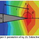
Numerical stress intensity factor for mode I crack opening can be evaluated using eq. (1) 3:
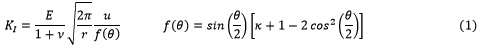
Figure 1: Parameters of eq. (1). Taken from 8
u half crack tip opening displacement;
 for plane stress.
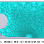
The FEM model has to be accurately prepared, with careful mesh refinement at the crack tip. Examples are shown in Figure 2. Plasticity at the crack tip can be taken into account.
Figure 2: Examples of mesh refinement at the crack tip.
Numerical crack grow rate evaluation
Crack grow rate can be evaluated by using theoretical models applied to the numerical results (numerical stress intensity factor range at the crack tip). Rupture occurs when , the threshold stress intensity factor, is reached. , applied stress intensity factor range, if a linear elastic behavior the following equations can be used:
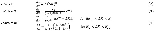
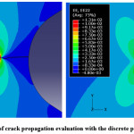
The parameters used in equations (2-4) can be found in the technical literature for many materials. Residual stresses can be taken into account by means of the application to the numerical model in the area in the proximity of the crack tip. Crack propagation has to be simulated in a discrete way (Figure 3).
Figure 3: Example of crack propagation evaluation with the discrete propagation method.
Confirmation of the numerical results: the replica method
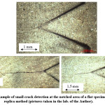
The replica method is accurately described in 8. Thin acetate strips, put for a short time in acetone, are positioned on the cracked area. A small finger pressure has to be applied on the strips in order to have the negative image of the crack. Small cracks can be detected and monitored (figure 4).
Figure 4: Example of small crack detection at the notched area of a flat specimen using the replica method (pictures taken in the lab. of the Author).
Crack gages for crack propagation evaluation
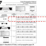
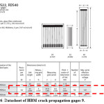
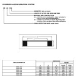
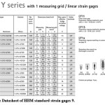
Crack gages are glued at the notch tip area of a dummy sample in order to record crack growth rate during the tests. These devices consist of a number of resistor strands connected in parallel in the direction transversal to the crack propagation. The propagation of the surface crack through the gage strands causes a crack propagation gage progressive open-circuit which results in a progressive variation of the total resistance. Two examples of crack propagation gage datasheets are reported in Figures 5 and 6 9, 10. The gages having the best resolution, i.e. 0.010 in (0.25 mm) and 0.004 in (0.1 mm), are evidenced. To improve the crack initiation detection both standard strain gage and specific crack detection gages are available (Figures 7 and 8) 10.
Figure 5: Datasheet of Vishay crack propagation gages 10.
Figure 6: Datasheet of HBM crack propagation gages 9.
Figure 7: Datasheet of Vishay crack detection gages 10.
Figure 8: Datasheet of HBM standard strain gages 9.
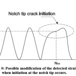
Both crack detection gages and crack propagation gages can be put on the sample at the notch tip. Using a standard strain gage the crack initiation can be also pointed out by detecting the presence of changes in the ε/N diagram. When such changes due to crack initiation occur, the strain vs. time or number of cycles diagram may show a local change like the one shown in Figure 9.
Figure 9: Possible modification of the detected strain when initiation at the notch tip occurs.
Conclusions
This paper reports the description of some numerical and experimental methods that allow to detect crack initiation and propagation. Numerical FEM models can be developed by using commercial codes. The crack replica method and crack propagation gages can be used to check and confirm the numerical results. The approach allows the designer to carry on a Fail-Safe design for critical components.
Funding source
The author declares that the funding is done by the author only.
Conflicts of interest
The authors have no conflicts of interest to disclose.
References
- T.L. Anderson, Fracture Mechanics, Taylor & Francis, 2005.
CrossRef
- S.M. Beden, S. Abdullah and A.K. Ariffin, Review of Fatigue Crack Propagation Models for Metallic Components, Eur. J. Sci. Res. 3, 364–397 (2009).
- M. Kato, G. Deng, K. Inoue, N. Takatsu, Evaluation of the Strength of Carburized Spur Gear Teeth Based on Fracture Mechanics, JSME Int. J., Ser. C, 36(2), 233–240 (1993).
CrossRef
- S.M. Beden, S. Abdullah, A.K. Ariffin, Review of Fatigue Crack Propagation Models for Metallic Components, Eur. J. Sci. Res., 3, 364–397 (2009).
- S. Baragetti, F. Villa, High-Strength Titanium Alloys Under Different Stress Gradients. The Journal of The Minerals, Metals & Materials Society (JOM), 67, 5: (2015).
CrossRef
- S. Baragetti, F. Villa, SCC and corrosion fatigue characterization of a Ti-6Al-4V alloy in a corrosive environment – experiments and numerical models. Frattura ed Integrità Strutturale, 8, 30, 84–9 (2014).
CrossRef
- S. Baragetti, F. Villa, “Quasi-Static Behavior of Notched Ti-6Al-4V Specimens in Water-Methanol Solution”. Corrosion Reviews, 33, 6, (2015).
CrossRef
- S. Baragetti, Numerical simulation of defects and inclusions in materials and components. Evolution in Polymer Technology Journal, 2(3): 180017, (2019).
- HBM website: https://www.hbm.com
- Vishay website: https://www.vishay.com

This work is licensed under a Creative Commons Attribution 4.0 International License.