Hamid Reza Ghazvinloo1*, Abbas Honarbakhsh-Raouf1 and Nasim Shadfar2
1Department of Materials Engineering, University of Semnan, Semnan, Iran.
2Oghab Afshan Indust. & Man. Co., Semnan, Iran.
DOI : http://dx.doi.org/10.13005/msri/070107
Article Publishing History
Article Received on : 12 Jan 2010
Article Accepted on : 10 Mar 2010
Article Published :
Plagiarism Check: No
Article Metrics
ABSTRACT:
Generally, the quality and properties of a weld joint is strongly influenced by welding variables during process. In order to achieve an ideal weld, it is important attention to bead geometry and microstructure evolution of weld metal. The effect of process variables on penetration and microstructure of C-80 steel joints produced by robotic CO2 arc welding was studied in present work. Different samples were produced by employing arc voltages of 23, 25 and 27 V, welding currents of 100, 110 and 120 A and welding speeds of 42, 62 and 82 cm/min. After welding process, geometric measurements were performed on welding specimens and the microstructural evolutions were investigated by optical observations of the weld cross sections. Results were clearly illustrated that increasing in welding current or arc voltage increases the depth of weld penetration. The highest penetration in this research was observed in 62 cm/min welding speed. The metallographic examinations also indicated that the microstructure of weld metal in all of specimens was composed mainly of martensite (M) and residual austenite (A) phases that a portion of martensite phase had been tempered.
KEYWORDS:
Welding parameters; Penetration; Microstructure; Heat input; Cooling rate
Copy the following to cite this article:
Ghazvinloo H. R, Honarbakhsh-Raouf A, Shadfar N. Effects of Robotic CO2 Arc Welding Variables on Penetration and Microstructure of Weld in C-80 Grade Steel. Mat.Sci.Res.India;7(1)
|
Copy the following to cite this URL:
Ghazvinloo H. R, Honarbakhsh-Raouf A, Shadfar N. Effects of Robotic CO2 Arc Welding Variables on Penetration and Microstructure of Weld in C-80 Grade Steel. Mat.Sci.Res.India;7(1). Available from: http://www.materialsciencejournal.org/?p=2223
|
Introduction
CO2 arc welding involves large number of interdependent variables that can affect product quality, productivity and cost effectiveness. The relationship between process variables and bead geometry are complex because of the number of variables and their interrelationships involved. Many attempts have been made to predict and understand the effect of the welding variables on the bead geometry. These include the entire theoretical studies based on heat flow theory1-2 and the empirical methods based on studies of actual welding applications.3-4 During the past 20 years significant progress has been made in understanding the solidification behavior of welds and the evolution of microstructure.5-6 Kacar and Kokemli7 studied on effect of controlled atmosphere on the MIG/MAG arc weldment properties. Muthupandi et al.8 researched on effect of weld metal chemistry and heat input on the structure of duplex stainless steel welds. Relationship between friction stir welding parameters and microstructure properties of AA6056 joints was studied by Cavaliere et al.9 Also effects of heat input on the microstructure of the 8 MnMoNi 5 5 shape-welded nuclear steel was predicted by Million et al.10 The present work is aimed at the evaluation of penetration and microstructure behavior of C-80 grade steel welded joints obtained by employing different arc voltages, welding currents and welding speeds.
Material and Methods
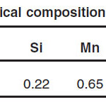
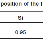
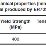
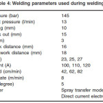
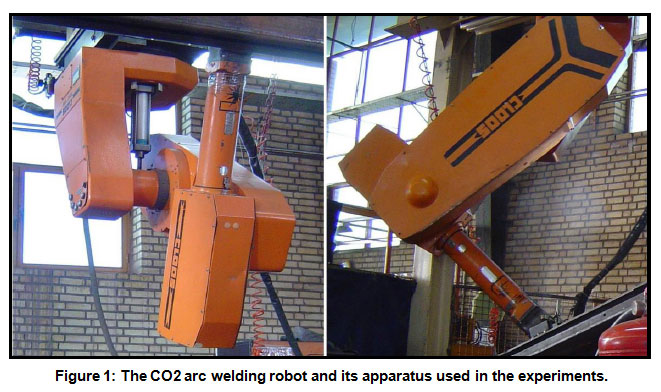
Due to high importance in industry, C-80 grade steel specimens having 4 mm thickness were used as base-metal in this study. The chemical composition of base metal was listed in Table 1. In addition, AWS A5.18: ER70S-6 wire electrode having 1.2 mm diameter was used as filling metal. The chemical composition of filler metal and minimum values for mechanical properties of produced weld metal by this filler metal were listed in Tables 2 and 3. CO2 arc welding process was used for joining the base metals. Robotic CO2 arc welding operations were performed by means of a SOS Model DR Series ARK ROBO 1500 welding robot having a working capacity of 0-600A and 0-50V ranges. The welding robot and its apparatus were shown in Fig. 1. For reduction welding distortion, before welding process, experimental test plates were fixed in the fixture jig. The chosen welding variables for this study were arc voltage, welding current and welding speed. The fixed parameters during welding and limits were given in Table 4. In order to investigate the relationship between the CO2 arc welding parameters and bead penetration, after the welding processes, the specimens were cut perpendicular to welding direction by using a closed circuit saw cooled by boron oil. For characterizing of weld microstructure in first, multipass welds cross-section were cleaned from each combination and grounded through 200-1000 mesh using grinding papers and then polished through 1µm diamond paste. The samples were etched in 2 % Nital for 6 s. In the present work, optical examination of samples was carried out using a OPT microscope. All experiments were performed at Semnan University in Iran during 2009.
Table 1: Chemical composition of base metal
Table 2: Chemical composition of the filler metal (ER70S-6)
Table 3: Mechanical properties (minimum values) for weld metal produced by ER70S-6 electrode
Table 4: Welding parameters used during welding
Figure 1: The CO2 arc welding robot and its apparatus used in experiments
Results and Discussion
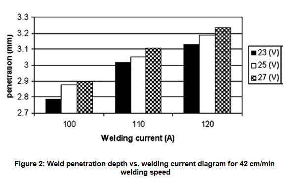
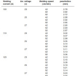
Experiments with employing different arc voltages, welding currents and welding speeds combinations were performed and the depth of penetration was measured for all cases. The results were tabulated as in Table 5 and Figs. 2-4.
Figure 2: Penetration depth vs. welding current diagram for 42 cm/min welding speed
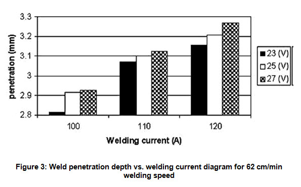
Figure 3: Penetration vs. welding current diagram for 62 cm/min welding speed
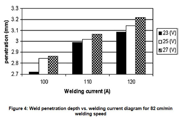
Figure 4: Penetration vs. welding current diagram for 82 cm/min welding speed
Table 5: Different conditions for welding
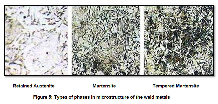
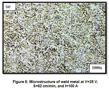
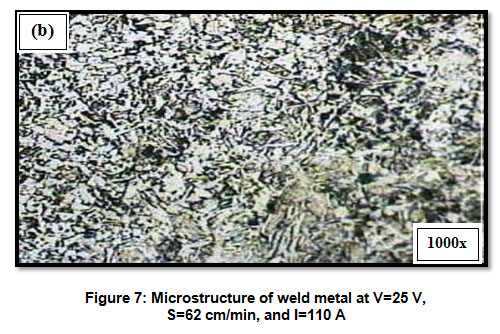
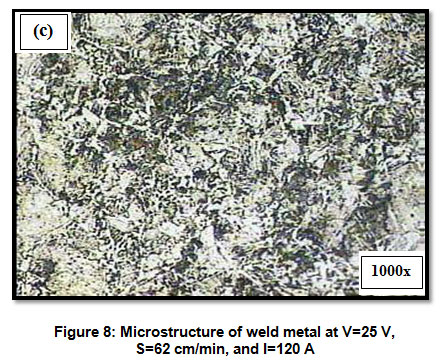
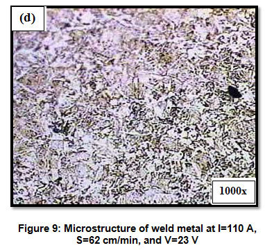
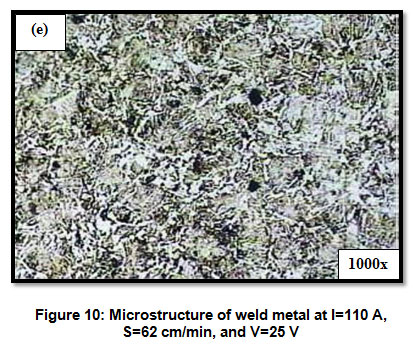
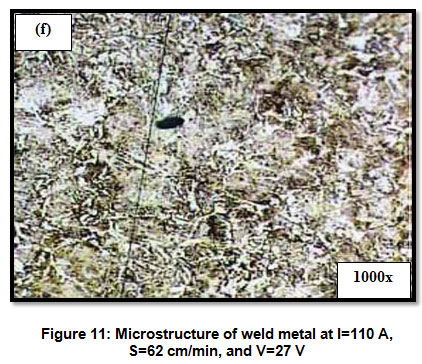
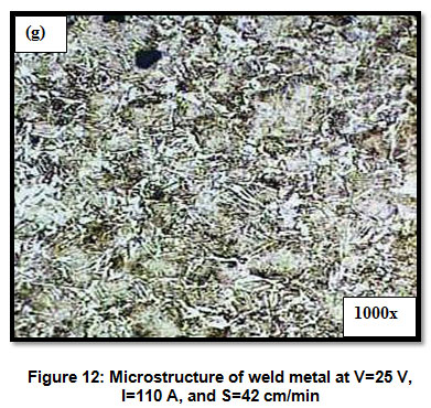
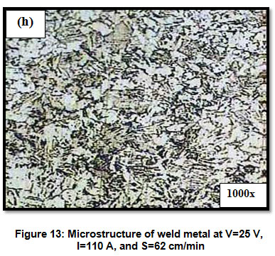
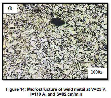
In Figs. 2-4, the welding speed was fixed as 42, 62 and 82 cm/min, respectively and the change in depth of penetration was drawn with welding current for 23, 25 and 27 V arc voltages values. A linear increase in depth of penetration with increasing welding current and arc voltage was observed commonly in all three different welding speeds. In Fig. 2, the welding speed was fixed as 42 cm/min. The deepest penetration value was obtained as 3.24 mm in 120 A and 27 V condition, while the smallest one as 2.78 mm in 100 A and 23 V. In Fig. 3, the welding speed was fixed as 62 cm/ min. The biggest penetration value was measured as 3.27 mm in 120 A and 27 V condition, while the smallest one as 2.82 mm in 100 A and 23 V. In Fig. 4, the welding speed was fixed as 82 cm/min. The deepest penetration value was obtained as 3.22 mm in 120 A and 27 V condition and the smallest one as 2.72 mm in 100 A and 23 V. This result is similar to the literatures.11-13 The depth of penetration increased with increasing welding speed up to 62 cm/min and reached to maximum value then began to decreasing after this point again linearly. These results are similar to the literatures.12-14 In continue the microstructural evolution of multiplass weld metal was analyzed by optical observations of the weld cross sections for all of the welding conditions. The metallographic results have been illustrated in Figs. 5-14. In attention to Figs. 6-14, the microstructures in weld specimens were composed mainly of martensite and residual austenite phases that a portion of martensite phase had been tempered. With increasing arc voltage and welding current or decreasing welding speed was increased the volume fraction of residual austenite and tempered martensite phases and coarsened a slight the microstructure in the weld metal. This evolution can be related to effects of welding parameters on cooling rate of weld metal. According to Eq. 1, welding heat input is increased with increasing arc voltage, welding current and with decreasing welding speed15:
H=60EI/(1000S) …(1)
Where,
H = heat input (kJ/mm)
E = arc voltage (volts)
I = current (Amp.)
S = welding speed (mm/min)
The most important characteristic of heat input is that it governs the cooling rates in welds metal.
The Eq. 2 shows this relationship between preheat temperature, heat input and cooling rate15:
R α 1/ (T0H) …(2)
Where,
R = cooling rate (°C/sec)
T0 = preheat temperature (°C)
H = heat input (kJ/mm)
The cooling rate in fusion welding is a primary factor that determines the final metallurgical structure and mechanical properties of the weld metal. Increasing of heat input and consequently decreasing the cooling rate for a given weld metal, promoted the formation of tempered martensite and residual austenite also significant coarsening was observed in the microstructure with increasing the heat input.
Figure 5: Phases types in microstructure evolution of the weld metals
Figure 6: Microstructure of weld metal for V=25v, S=62cm/min and I=100A 1000×
Figure 7: Microstructure of weld metal for V=25v, S=62cm/min and I=110A 1000×
Figure 8: Microstructure of weld metal for V=25v, S=62cm/min and I=120A 1000×
Figure 9: Microstructure of weld metal for, I=110A, S=62cm/min and V=23v 1000×
Figure 10: Microstructure of weld metal for, I=110A, S=62cm/min and V=25v 1000 ×
Figure 11: Microstructure of weld metal for, I=110A, S=62cm/min and V=27v 1000×
Figure 12: Microstructure of weld metal for V=25v, I=110A and S=42cm/min 1000×
Figure 13: Microstructure of weld metal for V=25v, I=110A and S=62cm/min 1000×
Figure 14: Microstructure of weld metal for V=25v, I=110A and S=82cm/min 1000×
Conclusion
The depth of penetration increases with increasing welding current between 100 and 120 A. In addition to welding current, increasing arc voltage between 23 and 27 V, also increases the penetration value. However, its effect is not as much as welding current. The deepest penetration in this study was obtained as 3.27 mm when the welding speed was 62 cm/min and the smallest penetration value was measured as 2.72 mm for 82 cm/min welding speed. The effect of welding current on penetration was greater than that of arc voltage and welding speed.
The microstructures in weld specimens produced by CO2 robotic welding process were composed mainly of martensite, tempered martensite and residual austenite phases that increasing in arc voltage and welding current or decreasing in welding speed increased the volume fraction of tempered martensite and residual austenite phases and coarsened a slight the microstructure in the weld metal.
Acknowledgements
The authors would like to thank of Industrial & Manufacturing Company of Oghab Afshan for their financial support and Semnan University for all the facilities.
References
- Rosenthal, D., “Mathematical theory of heat distribution during weld and cutting,” Weld. J., 20(5), 220-s–234-s (1941).
- Tsao, K. C., and Wu, C. S., 1988, “Fluid flow and heat transfer in GMAweld pools,” Weld. J., 67(3), 70-s–75-s.
- Drayton, P. A., “An examination of the influence of process parameters on submerged arc welding,” Welding Institute Research Report PE4/ 72 (1972).
- Yang, L. J., Chandel, R. S., and Bibby, M. J., “The effects of process variables on the weld deposit area of submerged arc welds,” Weld. J., 72(1), pp. 11–18 (1993).
- Badheshia, H. K. D. H., Svenson, L. E., and GretoftCross, B., Acta Metall, 33, 1271 (1985).
CrossRef
- Van der Eijk, C., Grong, Ö., and David, S.A., in: Proc. 5th International Conference on Trends in Welding Research, Georgia, USA, 1–5, ASM International, Materials Park, OH 44073-0002, USA (1998).
- Kacar, R., and Kokemli, K., “Effect of controlled atmosphere on the mig-mag arc weldment properties,” Materials and Design, 26, 508–516 (2005).
CrossRef
- Muthupandi, V., Bala Srinivasan, P.,Seshadri, S. K., and Sundaresan, S., “Effect of weld metal chemistry and heat input on the structure and properties of duplex stainless steel welds,” J. Materials Science and Engineering, A358, 9_/16 (2003).
- Cavaliere, P., Campanile, G., Panella, F., and Squillace, A., “Effect of welding parameters on mechanical and microstructural properties of AA6056 joints produced by Friction Stir Welding,” J. Materials Processing Technology, 180, 263–270 (2006).
CrossRef
- Million, K. Datta, R. and Zimmermann, H., “Effects of heat input on the microstructure and toughness of the 8 MnMoNi 5 5 shape-welded nuclear steel,” J. Nuclear Materials, 340, 25–32 (2005).
CrossRef
- Kim, I. S. and et al, “A study on relationship between process variables and bead penetration for robotic CO2 arc welding,” J. Material Processing Technology, 136, 139– 145 (2003).
CrossRef
- Tülbentci, K., “MIG-MAG arc welding,” Gedik Welding Co. Press, Istanbul, [in Turkish] (1990).
- Karadeniz, E., Ozsarac, U., and Yildiz, C., “The effect of process parameters on penetration in gas metal arc welding processes,” J. Materials and Design, 28, 649–656 (2007).
CrossRef
- Ates, H., and Türker, M., “Determination of penetration with various welding parameters of electrical arc and GMA welding” J. Gazi. Univ. 12, [in Turkish] (1999).
- Funderburk, S. R., “Key Concepts in Welding Engineering” Welding Innovation, 16(1): (1999).

This work is licensed under a Creative Commons Attribution 4.0 International License.