Residual Stress Measurements at the Interface of Spot Welded Dissimilar Metals Between Carbon Steel and Austenitic Stainless Steel
Triyono1*, Jamasri1, M. N. Ilman1, R. Soekrisno1 and M. Rifai2
1Mechanical Engineering Department, Gadjah Mada University, Yogyakarta, Indonesia.
2Neutron Scattering Laboratory, National Nuclear Energy Agency of Indonesia, Batan.
Corresponding Author E-mail: tyon_bila@yahoo.co.id
DOI : http://dx.doi.org/10.13005/msri/070201
Article Publishing History
Article Received on : 03 Feb 2010
Article Accepted on : 09 Mar 2010
Article Published :
Plagiarism Check: No
Article Metrics
ABSTRACT:
Residual stresses at the interface of spot welded dissimilar metals between carbon steel and austenitic steel have been studied. Carbon steel SS400 with thickness of 3.0 mm and 1.0 mm thick austenitic stainless steel SUS304 were joined in a lap joint by resistance spot weld (RSW). Residual stresses at the interface of spot welded similar metals 3.0 mm and 1.0 mm thick austenitic stainless steel SUS304 were also measured as a comparison. Neutron diffraction was used to determine the normal, radial and hoop residual stresses. Residual stresses, both on the side of carbon steel and stainless steel, either the normal, radial and hoop direction tend to compressive and vary depending on the distance from the nugget center. These stresses differ from the residual stresses at the interface of spot welded similar austenitic stainless steel that tend to tensile.
KEYWORDS:
Residual stress; Interface; Spot welded dissimilar metals; Neutron diffraction
Copy the following to cite this article:
Triyono, Jamasri, Ilman M. N, Soekrisno R, Rifai M. Residual Stress Measurements at the Interface of Spot Welded Dissimilar Metals Between Carbon Steel and Austenitic Stainless Steel. Mat.Sci.Res.India;7(2)
|
Copy the following to cite this URL:
Triyono, Jamasri, Ilman M. N, Soekrisno R, Rifai M. Residual Stress Measurements at the Interface of Spot Welded Dissimilar Metals Between Carbon Steel and Austenitic Stainless Steel. Mat.Sci.Res.India;7(2). Available from: http://www.materialsciencejournal.org/?p=2355
|
Introduction
Dissimilar metals between carbon steel and stainless steel has been widely used in engineering practice over the years such as railway car body, boilers and pipelines. To date the majority of welded structure was in the form of dissimilar metals because it is more economical in constructing a structure than using stainless steel only. Dissimilar metals weld is generally more challenging than that of similar metals weld because of differences in the physical, mechanical and metallurgical properties of the base metal to be joined.
The resistance spot welding (RSW) is the most important joining method for joining stiffened thin plate structures, especially in automotive, railroad, and airplane structures, which contain hundreds, even thousands of spot welds. According to studies, most of the welds used in an car body assembly are RSWs. The advantages of using spot welding are that it is a quicker joining technique, no filler material is required, and that the low heat input implies less risk for altered dimensions during welding. However, a spot weld provides a localized connection that it is a source of stress concentration, and thus fatigue crack initiation under fluctuating loading.1
In spot welding, a substantial residual stress field may develop as the process necessarily involves large temperature gradients from weld metal to bulk material. Since this residual stress affects the fatigue life of a welded component, it is essential to have precise knowledge of its distribution across the weld.2-6
Several methods are available for determining the residual stress. They include X-ray diffraction and hole drilling in conjunction with strain gauge measurements.7-8 Both methods are suitable only for surface measurements as X-rays do not penetrate far into most metals, and only a small hole depth is usually employed with the hole drilling technique. Recently a neutron diffraction procedure has been developed which allows through-thickness residual stresses to be determined without the need for destroying the component. It does, however, require the sample to be transported to a high flux neutron source. It has become a reliable and well-used technique to determine residual strains, and hence stresses, in crystalline materials. It remains the only technique capable of determining the residual stress field deep inside a polycrystalline material non-destructively.9-11
The critical area of spot welded joint called yield surface is around edge of nugget because fracture will initiate from this area.12 In the spot welded dissimilar metals and dissimilar in thickness, interface of joint is include the yield surface. The objective of this work was to investigate the residual stress at the interface of spot welded dissimilar metals between 3.0 mm carbon steel and 1.0 mm austenitic stainless steel.
Material and Methods
Carbon steel SS400 with the thickness of 3.0 mm and 1.0 mm thick austenitic stainless steel SUS304 were joined in a lap joint by resistance spot weld (RSW). RSW’s electrode had diameter of 25 mm and curved surface with a radius of 400 mm. Welding current and electrode force were 4.7 kA and 6 kN respectively. In this condition, formed nugget of RSW was 9 mm in diameter. As a comparison, spot welded similar metals 3.0 mm and 1.0 mm thick austenitic stainless steel SUS304 were made in the same condition.
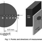
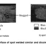
Residual stress measurements were taken from the center toward the edge of the nugget with radial distances of 1 mm respectively. Because of nugget symmetry, the measurement points have been represented residual stress distribution throughout nugget. Fig. 1 showed points and the schematic of three-axis measurement. The interface was defined as a boundary area between the two joined materials as shown in Fig. 2.
Figure 1: Points and directions of measurements
Figure 2: Interface of spot welded similar and dissimilar metals
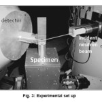
Neutron diffraction measurements were performed at DN-1 which was operated by National Nuclear Energy Agency of Indonesia (BATAN). It had a standard two-axis type diffractometer with a Si (311) monochromator system that is slightly bent horizontally and focused vertically to enhance the neutron flux at the sample position. The incident neutron beam was shaped by a 1 mm-wide, 5 mm-high slit to define the measurement gauge volume. The diffracted neutron beam passed a 1 mm-wide, 10 mm-high second slit and traveled toward a neutron detector which was centered at the scattering angel for the (111) and (200) diffraction of stainless steel and (110) and (200) diffraction of carbon steel. The specimen was mounted on an XYZ table and oriented to measure strains along the hoop, radial and axial directions, as illustrated in Fig. 3.
Figure 3: Experimental set up
The orientation of the principal strains was determined from the geometry. The strains (exx, eyy, ezz) could be converted to the three-dimensional stress (sxx, syy, szz) state. Equation (1) gave the stresses in three directions using the xx direction as an example.
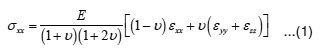
where E is Young’s modulus, and n is Poisson’s ratio.
Results and Discussion
The residual strains at the interface of spot welded dissimilar metals between carbon steel and austenitic stainless steel have been successfully measured with a gauge volume was defined above. Neutron beam was directed at the interface so that some gauge volume was in the stainless steel side and some other was in the carbon steel side. Carbon steel strain and stainless steel strain could be distinguished easily because they had a different scattering angle. Unlike spot welded dissimilar metals residual strain measurement, the spot welded similar metals residual strain measurement couldn’t definite which a part that diffracted neutron, because the thick and the thin stainless steel had same diffraction angle. It was assumed that a thick side scattered higher neutron intensity so measured strains were the thick stainless steel strains. These measured residual strains in three perpendicular directions then used to calculate the residual stresses.
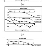
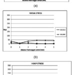
Fig. 4 and Fig. 5 compare the stress distributions measured at the interface of spot welded dissimilar and similar metals. The curves were created in the same scale to make clear comparison. The stress distributions at the interface of spot welded had the same pattern for all diffraction planes. However, the values of residual stress in different diffraction planes deviated by up to 100 MPa in dissimilar metals and 60 MPa in similar metals.
Figure 4: Residual stress distribution at the interface of spot welded dissimilar metal
Figure 5: Residual stress distribution at the interface of similar metal spot welded
In the spot welded dissimilar metals, the lowest compressive stress was at the nugget center and rose gradually to the nugget edge. In all directions, the stainless steel residual stresses were more compressive than carbon steel residual stresses. The residual stresses in normal and radial direction were more compressive than the residual stress in hoop direction. In the normal and radial direction, the mean carbon steel and stainless steel compressive residual stresses were 150 MPa and 250 MPa respectively. While in the hoop direction, the mean carbon steel and stainless steel compressive residual stresses were 25 MPa and 125 MPa respectively.
The stresses at the interface of spot welded similar metals were relatively less variable from the center to the edge of the nugget, either the normal, radial and hoop direction. These stress values ranged from -35 to +70 MPa. Although they deviated by up to 5 MPa, they showed reasonable agreement with the distributions of inner residual stress measured by XRD and by numerical analysis had been done by Anastassiou as stated by Bae.3 This discrepancy might be attributed to the different welding conditions and measurements. The suitability of residual stress measurement results of the spot welded similar metals to measurements made by Anastassiou, showed that the results of residual stress measurements at the interface of spot welded dissimilar metals were valid.
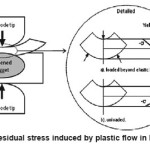
The differences of residual stress at the interface of spot welded similar and dissimilar metals, both value and pattern, were influenced by stresses worked at the interface during spot welding. The magnitude of these stresses was determined by physical, electrical, metallurgical and geometrical properties. The geometry which two plates with different thickness were joined, would cause a aberration of heat balance. Heat balance was defined as the conditions of welding in which the fusion zone of the pieces to be joined are subjected to equal heat and pressure.13 There might be a greater amount of localized heating in the thick plate than in the thin plat because the thick plate had the higher electrical resistance. Consequently, the asymmetry nugget was formed which the thick plat would have the wider part of nugget (Fig. 2). Another consequence of this condition was the bending load on the thin plate caused by electrode tip pressure. Fig. 6 illustrated the stress worked during the welding process. Stress at the interface of thin plat was tensile while in interface of thick plat was compressive. These stresses exceeded the yield limit and induced plastic deformation, because the yield limit dropped at welding temperature.14 After electrode pressure releasing and complete cooling, residual stress generated which was resultant of the bending stress in the thin plate and compressive stress in thick plate.
Figure 6: Residual stress induced by plastic flow in bending
Bending deformation at the interface of spot welded dissimilar metals was more obvious than bending deformation at the interface of spot welded similar metals (Fig. 2). The hardness difference was the reason. Carbon steel hardness was less than stainless steel hardness. This fact explained that the tensile stress at the interface due to bending load was greater than the compressive stress due to electrode pressure. Consequently, the compressive residual stress developed at the interface. While at the interface of spot welded similar metals, the electrode compressive stress was slightly larger than tensile stress due bending load. The low tensile residual stress would occur in this condition.
Conclusion
Stress at the interface of different thickness spot welded was the resultant of the tensile stress of thin plate due to bending load and compressive stress of thick plate due to the electrode pressure. In the spot welded dissimilar metals, tensile stress was greater than compressive stress, so residual stresses occurred was compressive stress, while in the spot welded similar metals, tensile stress due to bending was relatively equal to the electrode pressure so residual stress occurred was low tensile stress.
References
- Ertas, A.H. and Sonmez, F.O., Prooceedings of 8th International Fracture Conference, Istanbul, Turkey, 7 – 9 November 2007.
- Lin, Y.C. and Chen, S.C., Journal of Materials Processing Technology, 138: 22-27 (2003).
- Bae, D. H., Sohn, I. S. and Hong, J. K., Welding Journal, 18-s-23-s (2003)
- Sonsino, C.M., International Journal of Fatigue, 31: 88–101 (2009)
- Barsoum, Z., Engineering Failure Analysis, 15: 863–874 (2008)
- Sanjeev, K., Canlong, and Hari, A., Journal of engineering materials and technology, 123(1): 132-138 (2001)
- Hall, J. F. and Molkenthin, J. P., Proceedings of the Sixth International Symposium on Environmental Degradation of Materials in Nuclear Power Systems-Water Reactors, San Diego, CA, 855-861 (1993)
- Paynter, R., Mahmoudi, A. H., Pavier, M. J., Hills, D. A., Nowell, D., Truman, C. E. and Smith, D. J., Journal Strain Analysis, 44(1): 45-54 (2009).
- Pratihar, S., Stelmukh, V., Hutchings, M.T., Fitzpatrick, M.E., Stuhr, U. and Edwards, L., Materials Science and Engineering A, 437: 46-53 (2006)
- Law, M., Herold, T.G., Luzin, V. and Bowie, G., Physica B, 385: 900-903 (2006)
- Pearce S.V. and Linton, V.M., Physica B, 385: 590-593 (2006).
- Rusinski, E., Kopczynski, A. and Czmochowski, J., Journal of Materials Processing Technology, 157: 405-409 (2004).
- Schrader, G. F., Elshennawy A. K. and Doyle, L. E., Manufacturing processes and materials, Prentice-Hall. Inc, Michigan, 306-311 (2000)
- Radaj, H.D., Heat Effects of Welding; Temperature Field, Residual Stress, Distortion, Springer-Verlag, New York, 139-162 (1992).

This work is licensed under a Creative Commons Attribution 4.0 International License.