T. Ashokkumar1*, A. Rajadurai2 and Gouthama3
1Rajalakshmi Engineering College, Thandalam - 602 105, India.
2Madras Institute of Technology, Chromepet - 600 044, India.
3Indian Institute of Technology, Kanpur - 208 016, India.
DOI : http://dx.doi.org/10.13005/msri/080123
Article Publishing History
Article Received on : 01 Nov 2009
Article Accepted on : 19 Dec 2009
Article Published :
Plagiarism Check: No
Article Metrics
ABSTRACT:
Mechanical alloying through high energy ball milling was used to produce 40wt.%Ni-Fe alloy powder of average particle sizes 80 μm and 25 μm respectively. High Energy Planetary ball milling at room temperature was performed for various time durations of 16, 32 and 64 hours. Sintering was carried on DR.SINTER.LABTM (SPS 515S) machine. Samples were sintered at constant temperature of 650°C and pressure of 30 MPa for all samples. This study exhibits in same alloy, but increases of milling hours, the densification of the sintered samples decreases and also porosity of the sample increases. This may be due to the reasons of increases in the surface area of the milled nanopowder (ie. Reduction of particle size), low green body density of long milling powders by agglomeration of powders and oxidation of powders during a milling process. However, this study revealed that in the same alloy with increasing milling hours, required more temperature and pressure for perfect densification. Densification of 85.4 % was achieved in 16 hours milled sample.
KEYWORDS:
Mechanical alloying; Particle size; Morphological study; Microstructure; Recrystallization; Spark plasma sintering (SPS)
Copy the following to cite this article:
Ashokkumar T, Rajadurai A, Gouthama. A Study on Ni-Fe Ball Milled Spark Plasma Sintered Sample. Mat.Sci.Res.India;8(1)
|
Introduction
Ni-Fe alloy of varying compositions are extensively used in electromagnet due to their low hysterices loss, high permeability and high saturation flux density. Their mechanical properties can be improved using several techniques such as recrystallization,1 solid state sintering,2 cyclic heat treatment,3,4 formation of matrix pools,5 surface carburization,6 formation of irregular particle shape7 and mechanical alloying.8 During the last few years, major advances have been made in the study of the behavior of small particles due to their enhanced properties. The mechanical alloying process developed by Benjamin,9 an advanced fabrication process which can produce very fine and homogenous powder. Mechanical milling has been suggested as a process to develop alloys with improved mechanical properties and Magnetic properties.10 Spark plasma sintering is the latest high speed sintering process and it is the low power consumption and energy saving process.11,12 This study reveled that, effect of mechanical alloying and sintering behavior of mechanical alloyed 40wt.% Ni-Fe nanopowder with varying milling hours.
Material and Experimental
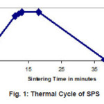
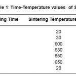
Elemental powders of Nickel and Iron with the purity of 99.8% and 99.5%, particle size 80 µm and 25 µm and grain size 280 nm and 160 nm respectively were used as the starting material. Powder mixture of 40wt.% Ni-Fe was selected as the starting material and it was milled at 16, 32 and 64 hours duration. High Energy Planetary ball milling was performed in the laboratory planetary mill (RETSCH) with ball to powder mass ratio of 10:1 at a speed of 300 rpm, using stainless steel jars and balls. The jars were sealed under atmospheric pressure and temperature. Toluene was used as a process control agent. DR.SINTER.LABTM (SPS 515S), apparatus was used for sintering of samples. Graphite punches and die were used. Cylindrical shape of 12 mm diameter and 5 mm height samples were made. Thermal Cycle of SPS is shown in Figure 1 and time-temperature values of SPS are listed in Table 1.
After reaching 650°C the sample was kept for 5 minutes holding and then the sample was free cooled at inside the furnace. 30 MPa compression pressure was applied during the heating steps and used vacuum pressure was 6 Pa while sintering. Characterization was carried out for milled powders and sintered samples. Phases and micro structures were analyzed by X-Ray Diffraction (XRD) using SIETRONICS XRD SCAN Diffraction meter as Cu-Ká target was used with a radiation of 1.541841 A°. Powder morphological images were taken under varying milling hours by Scanning Electron Microscopy. The average grain size was calculated from XRD images using Scherrer’s equation13, 14 as D = Kλ / (β cos θ), where D is the average grain size, l is the X-ray wave length , θ is the Bragg angle, β is the finite-size broadening and K is a constant close to unity. Mastersizer Particle Size Analyzer was used to measure the particle size. Volume fraction of porosity was calculated by P = 1- ( α / µ ), where α is the actual density of the alloy and µ is the theoretical density of the alloy. The density was measured using Archimedes principle with water as the liquid medium.
Figure 1: Thermal Cycle of SPS
Table 1: Time-Temperature values of SPS
XRD Pattern
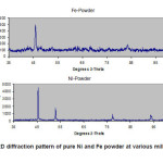
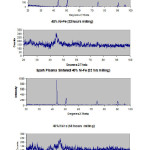
The XRD spectra of Fe and Ni are shown in Figure 2 and those of 40% Ni-Fe powder and spark plasma sintered samples at various milling hours are shown in Figure 3. From Figures 2 and 3, in the case of powder sample, it could be observed that the X-ray diffraction peaks widen as the milling time increases and in case of sintered sample X-ray diffraction peak narrow down as the milling time increases. Former could be explained as due to the refinement of grain size and increases of micro strain during mechanical alloying and later is grain growth due to the application of temperature and pressure while sintering.
Figure 2: XRD diffraction pattern of pure Ni and Fe powder at various milling hours
Figure 3: XRD diffraction pattern of 40%Ni-Fe powder and Spark Plasma sintered samples at various milling hours
Grain Size
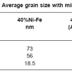
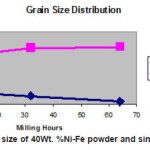
The average grain sizes were calculated from the super imposed XRD (111) peak of Ni and (110) peak of Fe using Scherrer’s equation.13, 14 The variation of the grain size with milling hour is listed in Table-2 and graphically shown in Figure 3. It can be seen that in powder sample the grain size decreases with increase of milling hours and reaches 18.5 nm at 64 hours of milling, in sintered sample the grain size increases with increase of milling hours.
Table 2: Average grain size with milling time
Figure 4: Grain size of 40Wt. %Ni-Fe powder and sintered samples
Morphological Study
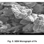
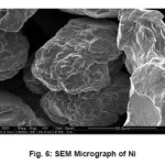
Fig.5 and 6 shows the SEM images of pure Iron and Nickel respectively. Fig.5 exhibits the sub angular particle of various sizes, while Fig.6 shows large lumps of spherical particle of uniform size. The average particle size of Fe is 24 µm while that of Ni is 79 µm.
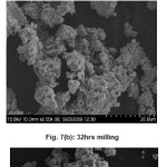
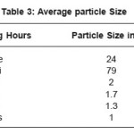
The morphology of 40% Ni-Fe powders at different milling times was investigated using SEM analysis. Fig. 7 A to 7 D shows the morphological development of the particles from 16 to 100 hours of milling. The values of average particle size of different milling hours are listed in Table 3. It can be seen from Fig.7 A that at 16 hours of milling the mixture consists of both fine and large size particles. Further milling up to 32 hours has resulted fracturing of only the largest particles and hence the particle size keep on decreasing. Figure 7 B to 7C show that the particle size decreases till the particle size is the lowest at 64 hours of milling is 1.3 µm. This is because of the fracturing force dominate the cold welding force while milling ranges from 16 to 64 hours.
Figure 5: SEM Micrograph of Fe
Figure 6: SEM Micrograph of Ni
Figure 7: SEM Micrograph of 40wt.% Ni-Fe with different milling hours
Table 3: Average particle Size
Densification
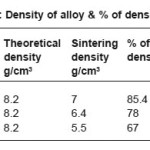
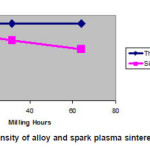
Theoretical density, sintering density and % of densification are listed in Table 4 and graphically shown in Fig 8. The Calculated value of theoretical density of 40%Ni-Fe alloy is 8.2 g/cm3. It could be observed from Fig 8 milling hour increases (reduction in grain size) density of sintered sample and % of densification decreases. This indicates while grain size decreases more temperature and pressure required for better densification. This may be due to the reasons of increases in the surface area of the milled nanopowder (ie. Reduction of particle size), low green body density of long milling powders by agglomeration of powders and oxidation of powders during a milling process. Increases the surface area of the powder particle causes the more heat transfer.
Table 4: Density of alloy & % of densification
Figure 8: Density of alloy and spark plasma sintered sample
Porosity
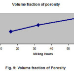
Volume fraction of porosity is listed in Table 5 and graphically represented in Fig 8. It can be seen from Table 5 and Fig 9 milling hour increases the volume fraction of porosity also increases
Figure 9: Volume fraction of Porosity
Conclusion
Mechanical alloyed 40wt.%Ni-Fe of Four different milling hours powder samples and SPS sintered samples were characterized by using X-ray Diffraction, Scanning Electron Microscope and Particle Size Analyzer. The main conclusions drawn from the study are:
In powder sample the grain size decreases with increase of milling hour and it reaches 18.5 nm at 64 hours of milling.
In Spark Plasma Sintered sample, the grain size increases with increase of milling hour.
Milling hour increases, the volume fraction of porosity also increases.
Milling hour increases, (reduction in grain size) density of the sintered sample and % of densification decreases. This indicates while grain size decreases more temperature and pressure required for better densification. This may be due to the reasons of increases in the surface area of the milled nanopowder (ie. Reduction of particle size), low green body density of long milling powders by agglomeration of powders and oxidation of powders during a milling process. Increases the surface area of the powder particle causes the more heat transfer. Densification of 85.4% was achieved for 16 hours of milled sample.
Acknowledgment
The authors wish to thank the management of Rajalakshmi Engineering College for permitting the author to do the experimental analysis in IIT.Kanpur on duty. Thanks are due to IIT, Kanpur for permitting the author to use their experimental facilities such as SEM, XRD, Particle size analyzer and Ball milling without which this work could not have been possible.
References
- Goren-Muginstein, G.R and Rosen, A. ‘The effect of cold deformation on grain refinement of heavey metals’, Mater.Sci. Eng, 238: 351 (1997).
CrossRef
- Ryu, H.J, Hong, S.H. and Back, W.H., ‘Microstructure and mechanical properties of mechanically alloyed and solid state sintered tungsten heavy alloys’, Mater,Sci. Eng. A, 291: 91 (2000).
CrossRef
- Joon-Woong noh, Eun-Pyo kim, Heung-Sub Song,Woon-Hyung Baek, Kil-Sung Churn, and Suk-Joong L. kang, ‘Matrix penetration of w/w grain boundaries and its effect on mechanical properties of 93W-5.6Ni-1.4Fe heavy alloys’, Metall. Trans.A, 24: 2411 (1993).
- Joon-Wong Noh, Moon-Hee Hong, Geun-Hong Kim, Suk-Joong L. Kang, and Duk Yong Yoon, ‘The cause of matrix penetration of W/W grain boundaries during heat treatment of W-Ni-Fe hevy alloy’, Metall. Trans, A, 25:2828 (1994) .
CrossRef
- Hong, S.H, Ryu, H.J and Baek W.H, ‘Matrix pools in partially mechanically alloyed tungsten heavy alloy for localized shear deformation’, Mater. Sci. Eng. A, 333: 187(2002).
CrossRef
- Jung, S.h, Kim, D.k.Lee, S et al., ‘Effect of surface carburization on dynamic deformation and fracture of tungsten heavy alloy’, Metal. Mater. Trans. A, 30: 2027 (1999).
CrossRef
- Song, H.S, Noh, J.W and Baek, W.H et al.,‘Undulation of W/Matrixinterface by resintering of cyclically heat-treatedW-Ni-Fe heavy alloys’, Metall. Trans.A, 28: 485 (1997).
CrossRef
- Ryu, H.J, Hong, S.H and Baek, W.H,‘Combination of mechanical alloying and twostage sintering of a 93W5.6Ni1.4Fe tungsten heavy alloy’, Mater.Sci.Eng.A, 344: 253 (2003).
CrossRef
- Benjamin, J.S, ‘Dispersion strengthened super alloys by mechanical alloying’, Metall.Trans.A, 1: 2943 (1970).
- Ashokkumar T, Rajadurai A, Gouthama and Sampath, S, ‘Effects of mechanical alloying on microstructure, morphology and magnetic properties of 40%Nii-Fe nanopowder’Material Science Research India, 2: 283-292 (2008).
- M. Tokita J. Soc. Powder Technol. Jpn. 30:790 (1993).
CrossRef
- M. Tokita Proc. Powder Metall. World Congr.Kyoto, Japan, part 1: 252 (2000).
- Carmen A. Huber, ‘X-Ray Diffraction Characterization of Nanophase Materials’, National Science Foundation, Arlington,Virginia, ISBN 0-333-56814-1: 325 (1992).
- Islam, S, Humail, Xuanhui Qu, Chengchang Jia, Mingli qin, and Xinbo He, ‘Morphology and microstructure characterization of 95W-3.5Ni-1.5Fe powder prepared by mechanical alloying’, Materials, 13: 442 (2006).

This work is licensed under a Creative Commons Attribution 4.0 International License.