S. N. Singh, Manish Kumar, Subhash Kumar and Mamta Kumari
Department of Physics, C.M.Sc. College, Darbhanga, India.
Department of Physics, L.N.Mithila University, Darbhanga - 846 004, India.
DOI : http://dx.doi.org/10.13005/msri/080117
Article Publishing History
Article Received on : 06 Jan 2011
Article Accepted on : 08 Feb 2011
Article Published :
Plagiarism Check: No
Article Metrics
ABSTRACT:
In this communication, several coplanar wave guide topologies to the hemispherical DR.A are presented. It is seen that the inductive and the circular-loop CPW feed configurations offer the flexibility to excite the fundamental TE111 resonant mode of the hemispherical DRA close to the source free resonant frequency, due to the presence of metallization in the coupling region. Dual-band behavior is observed with the capacitive feed due to the DRA and slot resonant modes, which are displaced with respect to the unperturbed modes due to the uninterrupted slot. The radiation characteristics of the antenna arc also explained.
KEYWORDS:
Capacitive; Coplanar waveguide (CPW); Circular-loop; Dielectric resonator; Inductive
Copy the following to cite this article:
Singh S. N, Kumar M, Kumar S, Kumari M. Coplanar Waveguide Feed to the Hemispherical DRA. Mat.Sci.Res.India;8(1)
|
Introduction
The dielectric resonator antenna (DRA) has emerged as an efficient and broad-band radiating source primarily due to the absence of metallization. In this communication, the design of a uniplanar coplanar waveguide (CPW) feed configuration to the hemispherical DRA is presented.
The CPW feed to the DRA was reported in1 for a cylindrical DRA and in2 for a rectangular DRA configuration. The performance of three different CPW feed types to the rectangular DRA was compared in.3
In this work, the characteristics of the hemispherical DRA fed by the three different CPW feed configurations, viz. the inductive, capacitive and circular-loop feeds are presented. It is seen that the coupling behavior of the above CPW feed topologies to the hemispherical DRA is quite different from the CPW feed to the rectangular DRA in.3
Also, the inductive and the circular-loop feeds are most effective to excite the DRA very close to the unloaded resonance frequency of the TE111 mode, which is particularly advantageous for the antenna designer. This is due to the presence of metallization in the coupling region of the inductive and the circular-loop feeds.
Dual-band behavior is observed for the capacitive feed to the hemispherical DRA due to the DRA and slot resonances. However, the DRA and the slot resonant frequencies with the capacitive feed are displaced from the free DRA and slot resonances respectively, due to the presence of the uninterrupted slot. In addition, the smaller size of the circular-loop feed to the hemispherical DRA allows this feed to be fabricated on a lower permittivity substrate with reduced stir- face-wave loss.
CPW Feed Topologies
Inductive Feed to the Hemispherical DRA
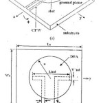
The CPW inductive feed to the hemispherical DRA is shown in Fig. 1. The radius of the hemispherical DRA is a = 12.70 mm with a dielectric constant of 20 which were chosen to excite the fundamental TE111 resonant mode. The substrate material is Rogers RT6010LM, with length (Ls) and width (Ws) of 230 mm each, a thickness of 2.54 mm and a dielectric constant of 10.20.
The trace width of the CPW line and the gap between the CPW trace and the ground plane are chosen to be S = 1.40 mm and G = 0.625 mm respectively with a slot length and width of Lind = 14.50 mm and Wind = 0.625 mm respectively. Identical dimensions and permittivities for the DRA, the CPW line and the substrate have been used throughout in this work.
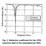
The measured and simulated reflection coefficients for the CPW inductive feed to the DRA is shown in Fig. 2. The simulated results have been obtained using CST Microwave Studio.4 The resonance in the simulated reflection coefficient is observed at 2.50 GHz which is very close to the source free resonant frequency of 2.55 GHz of the TE111 mode of the DRA.
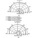
The measured and simulated antenna radiation patterns are shown in Fig. 3. The E and H-planes in the radiation pattern are the x-z and y-z planes respectively. The radiation pattern characteristics are determined principally by the modal field configuration of the TE111 resonant mode for the DRA (Figs. 7(a) and 13(a) 5).
It is noted that the E-plane radiation pattern in Fig. 3(a) at θ = 00 differs slightly from the broadside radiation characteristics of the TE111 mode. This is probably caused by the feed radiation and also due to the finite ground plane.
It is observed that the cross-polar level in both the E and H-planes is under –30 dB. Due to the inductive slot configuration, the mechanism of coupling between the DRA and the CPW line is magnetic in nature, as explained in.3 In addition, the magnetic field lines of the TE111 mode in the centre of the DRA on the x-y plane are y-directed, as can be seen from Fig. 13(a), 5. This matches with the orientation of the magnetic field due to the induced current in the central region of the inductive slot and also with the magnetic field lines in the rest of the CPW line underneath the DRA. As a result, the H-plane cross-pol level is very low.
Capacitive Feed to the Hemispherical DRA
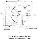
The capacitive feed configuration to the DRA is shown in Fig. 4. The CPW slot length is adjusted to Lcap = 14.30 mm with the slot width Wcap the same as for the inductive feed. Due to the uninterrupted slot in this case, the dominant coupling mechanism between the CPW slot and the DR.A mode in this case is electric in nature, as explained in.3 Particularly, a comparison of the electric field configuration of the TE111 mode in Fig. 7(a),5 and the slot electric field across the slot-width shows perfect match between these two fields. Also, as noted before for the inductive feed, the electric fields in the CPW line in the vicinity of the slot also have an effect un the coupling between the CPW line and the DRA due to the uniplanar configuration of the CPW line.
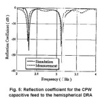
Moreover, a dual-resonance characteristic is observed in the plot for reflection coefficient in Fig. 5. The location of the first resonance in the simulated results is at 2.30 GHz. However, this resonance is shifted from the unperturbed resonance of the TE111 mode at 2.55 GHz due to the loading effect of the CPW slot and the CPW line in the vicinity of the slot. A second resonance is seen to occur at 3.13 GHz. This is caused due to slot-resonance.
Taking into account the substrate permittivity of 10.2 below the slot and the presence of a homogeneous and uniform dielectric slab of permittivity 20 above the slot, the slot-resonance is found to be at
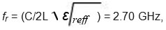
where Σreff is the average of the substrate and the DRA permittivities. The slot-resonance is displaced to 3.13 GHz due to the presence of the finite dielectric material of the DRA and is also influenced by the CPW line near the slot.
It might be noted that due to the presence of the metallization in the central region of the coupling slot in case of the inductive feed, the influence of the slot or the CPW line near the slot is much less significant on the position of the resonant dip from the free TE111 resonance of the DRA. In contrast, due to the unperturbed slot in the capacitive feed, additional slot resonance is observed together with the DR.A resonance Moreover, both the DRA and slot resonances are shifted from their free, resonance values. This is particularly important as similar control on resonance behavior and coupling mechanism by the modification the configuration of the coupling slot is not possible in the case micro strip slot-coupled configuration. As the fields are strongest in the coupling region which is metallized in case of the inductive feed, the image of the hemispherical DRA on the ground plane is relatively Unperturbed for the inductive feed. This results in excitation of the DRA close to the free resonance frequency. The perturbation of the DRA image due to the uninterrupted slot on the ground plane is more for the capacitive feed, which causes the shift in DRA resonance.
It is thus observed that the inductive or capacitive feed architectures to the hemispherical DRA ca be chosen depending on whether the DRA needs to be excited close to the fundamental mode or dual-band operation is desired.
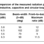
The E- and H-plane radiation patterns for the capacitive feed were measured at the first and second resonant frequencies. While the patterns at the first resonant frequency are similar to Fig. 3, the feed radiation in the E-plane at è = 00 is absent for the second resonance. Table I compares the measured radiation performances of the CPW feed configurations discussed in this communication. The front-to-back ratio for the second resonance of the CPW capacitive feed is seen to be poorer which is characteristic of a relatively omnidirectional pattern due to slot resonance. The slightly higher H-plane cross-pot for the capacitive feed compared to the case of the inductive feed can be explained by the orientation of the electric field lines in the slot region and its vicinity
Table 1: Comparsion of the measured radiation performance of the inductive, capacitive and circular-loop peeds
Figure 1: CPW inductive feed to the hemispherical DRA. (a) 3E view and (b) x-y plane
Figure 2: Reflection coefficient for the CPW inductive feed to the hemispherical DRA.
Figure 3: Radiation patterns of DRA at resonance with CPW inductive feed. (a) E-plane. (b) H-plane
Figure 4: CPW capacitive feed to the hemispherical DRA
Figure 5: Reflection coefficient for the CPW capacitive feed to the hemispherical DRA
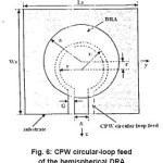
Figure 6: CPW circular-loop feed of the hemispherical DRA
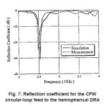
Figure 7: Reflection coefficient for the CPW circular-loop feed to the hemispherical DRA
Circular-Loop Feed to the Hemispherical DRA
The CPW circular-loop feed to the hemispherical DRA is shown in Fig. 6. The CPW circular-loop feed possess an inner radius of r1 = 3.50 mm and an outer radius of r2 = 4.125 mm, and is offset by c = 2.50 mm from the DRA centre. The resonant frequency for this feed is seen at 2.53 GHz from the plot for reflection coefficient in Fig. 7, which is close to the free TE111 mode resonance, similar to the inductive feed. This can be attributed to the central circular region of metallization of radius r1 in the circular-loop feed which couples to the DRA mode.
In comparison to the inductive or capacitive feeds, however, the size of the circular-loop feed is smaller, due to its curved shape. This enables design of the circular- loop feed on low-permittivity substrates while being totally covered by the DRA. The coupling nature for this feed is also magnetic in nature, due to the circular region of metallization in the feed connected to the CPW trace.
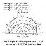
The E-plane pattern for the circular-loop feed is similar to Fig. 3(a). The H-plane pattern for this feed is shown in Fig. 8. It can be seen from Fig. 8 and Table I that compared to the inductive or capacitive feeds to the hemispherical DRA, the H-plane cross-pol level is higher in this case, with the maximum H-plane cross- po1 at around -14 dB. It should be noted that the circular-loop feed is offset from the DRA centre, unlike the inductive and capacitive feeds. Also, the central coupling region of area π r 12 = 38.48 mm2 for the circular-loop feed is much larger than the central coupling region of area S×Wind = 0.875 mm2 for the inductive feed. On examination of the magnetic fields of the TE111 DRA resonant mode in Fig. 13(a), [5], it can be seen that as a result of the offset and the larger coupling area for the circular-loop feed, the magnetic fields of the TE111 mode are no longer linearly oriented in this region, which prevents the magnetic fields of the circular-loop feed from exactly matching to the magnetic field of the DRA mode over the larger coupling area.
It has also been seen that though dual-band is observed for the CPW capacitive feed to the rectangular. DRA, the coupling is poorer compared to the CPW capacitive feed to the hemispherical DRA. In addition, the presence of two separate resonances depending on the capacitive slot length in the case of the rectangular DRA [3] has not been observed for hemispherical DRAs. Also, the H-plane cross-pol is higher in the circular-loop feed .o the hemispherical DRA compared to the square loop feed to the re’.angular DRA, due to the feed offset in the former case.
Figure 8: H-plane radiation pattern o C ‘7.A at resonance with CPW circular-loop feed
Conclusion
In this communication, the excitation of the fundamental TE111 mode of the hemispherical DR. using several CPW feed topologies is investigated. It is seen that the inductive and the circular-loop feeds results in easy excitation of the ERA resonant mode close to its unperturbed resonance, due to the presence of metallization in the coupling region. The capacitive feed however possesses dual resonance due to the DRA and the slot resonance modes. These modes are also shifted with respect to the unloaded DRA and slot modes respectively due to the uninterrupted slot. The radiated field patterns are also explained by considering the coupling to the DRA mode.
References
- R. A. Kranenburg, S. A. Long, and J. T. Williams, “Coplanar wave- guide excitation of dielectric resonator antennas,” IEEE Trans. Antennas Propag., 39: 119-122 (1991).
CrossRef
- M. S. Al Salameh, Y. M. M. Antar, and G. Seguin, “Coplanar-waveguide-fed slot-coupled rectangular dielectric resonatorantenna,” IEEE Trans. Antennas Propag., 50:1415-1419 (2002).
CrossRef
- B. Ghosh, Y. M. M. Antar, A. Petosa, and A. Ittipiboon, “CPW feed to rectangular DRA,”Microw. Opt. Tech. Lett., 45: 210-216 (2005).
CrossRef
- CST Microwave Studio. Darmstadt, Germany: Computer Simulation Technology GmbH, 2006.
- A. A. Kishk, G. Zhou, and A. W. Glisson, “Analysis of dielectric-resonator antennas with emphasis on hemispherical structures,” IEEE Antennas Propag. Mag., 36: 20-31 (1994).
CrossRef

This work is licensed under a Creative Commons Attribution 4.0 International License.