Effect of Friction Stir Welding Processing Parameters on Abrasion Wear Resistance of AA5083 Welded Joints
O. Badran1, N. Al-Kloub2*, A. Mahmood Hassan2, J. Abdullah Al-Jarrah3 and S. Khaled Khrais4
1Dean's Assistant for Scientific Research and Graduate Studies, Faculty of Engineering Technology, Al-Balqa Applied University, PO. Box 330116, Amman - 111 34, Jordan.
2Al-Balqa` Applied University, Faculty of Engineering Technology, Amman, Jordan.
3Jordan University of Science and Technology, Industrial Engineering Department, Irbid, Jordan.
4Al-Balqa` Applied University, Al-Hosun College, Irbid, Jordan.
DOI : http://dx.doi.org/10.13005/msri/080104
Article Publishing History
Article Received on : 10 May 2011
Article Accepted on : 20 June 2011
Article Published :
Plagiarism Check: No
Article Metrics
ABSTRACT:
The effect of processing parameters an abrasion wear resistance of AA5083 joints produced by FSW was analyzed in this study. Welding speed and rotational speed were the considered parameters studied in this investigation at five levels for each one. The result of this study showed that the abrasion wear resistance of the stir zone increased with increasing welding speed and it increased with decreasing rotational speed. And that welding speed is more significant than rotational speed. Also, the interaction effect of welding speed and rotational speed is not significant.
KEYWORDS:
Abrasion wear resistance; Friction; Stir welding processing
Copy the following to cite this article:
Badran O, Al-Kloub N, Hassan A. M, Al-Jarrah J. A, Khrais S. K. Effect of Friction Stir Welding Processing Parameters on Abrasion Wear Resistance of AA5083 Welded Joints. Mat.Sci.Res.India;8(1)
|
Copy the following to cite this URL:
Badran O, Al-Kloub N, Hassan A. M, Al-Jarrah J. A, Khrais S. K. Effect of Friction Stir Welding Processing Parameters on Abrasion Wear Resistance of AA5083 Welded Joints. Mat.Sci.Res.India;8(1). Available from: http://www.materialsciencejournal.org/?p=2462
|
Introduction
Aluminum has many attractive properties compared to steel, it is economical and versatile to use that is the reason it is used a lot in the aerospace, automobile and other industries.1 The most attractive properties of aluminum and its alloys which make them suitable for a wide variety of applications are their light weight, appearance, fabric ability and strength. The important property of aluminum is its ability to change its properties in a very versatile manner; it is amazing how much the properties can change from the pure aluminum metal to its most complicate alloys. There are more than a couple of hundreds alloys of aluminum. There are many different methods available for joining aluminum and its alloys, welding is one of the most used methods for joining aluminum alloys. Most alloys of aluminum are easily weld able. Fusion welding such as MIG and TIG are the most welding processes used, but there are some problems associated with this welding process like porosity, lack of fusion due to oxide layers, incomplete penetration, cracks, inclusions and undercut. Aluminum alloys can be joined by solid state welding such as resistance welding, friction welding and laser welding.2,3
Friction stir welding (FSW) is a solid state welding process and it considered to be the most significant development in metal joining techniques in a decade, it was invented at The Welding Institute (TWI) of UK in 1991 as a solid-state joining technique, and it was initially applied to aluminum alloys.3-5
Three distinct zones, the stirred zone (SZ), the thermo mechanically affected zone (TMAZ) and the heat-affected zone (HAZ) – are identified in FSW aluminum alloys based on micro structural characterization of grains. The stirred is the region through which the tool piece pin passes, and thus intense plastic deformation and frictional heating during FSW happened which result in generation of a recrystallized fine-grained microstructure, the thermo mechanically affected zone is a transition zone between base metal zone and nugget zone and it usually refers as (TMAZ). This zone experiences both temperature and plastic deformation but this deformation strain is insufficient to induce recrystallization, the heat affected zone is a zone experience a temperature rise; it’s retaining the same grain structure as the parent material.3, 6
Wear occurs in many different industrial situations, and causes high costs due to equipment failures, replacement of wear parts and downtime during repairs. In addition, the wear influences the quality of the products involved. Wear can be classified into different modes. One common division is adhesion, abrasion, surface fatigue and tribochemical reaction.7 These wear modes can be divided furthermore into different wear mechanisms. Abrasion may occur by microploughing, micro cutting, micro fatigue and micro cracking.7 In the simplest case, only one type of wear mechanisms is present. However, usually several wear mechanisms occur at the same time.8, 9
In this study, materials of interest are AA5083 friction stir welded joints. The aim of this study is to investigate the effect of processing parameters, welding speed and rotational speed, on abrasive wear performance of the stir zone in the welded joints. The wear resistances of the studied joints are tested by dry sand rubber wheel abrasion test (ASTM G65-00).
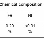
Table 2.1: Chemical composition of Al alloy
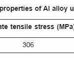
Table 2.2: Mechanical properties of Al alloy used in the experiment
Materials
The chemical nominal composition of 5083A alloy base material used in this investigation is presented in table 2.1. The welds were produced in 6 mm thick plates with mechanical properties shown in table 2.2.
Welding Equipment
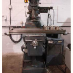
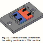
A conventional vertical milling machine shown in figure 2.1 was transformed into a friction stir welding machine by designing a fixture that makes the milling machine capable of performing friction stir welding process. The fixture used in the process was designed to be firmly clamped the specimen during the process as shown in figure 2.2
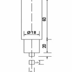
The tool used for FSW process is a high carbon steel with square pin profile which was recommended by several workers [3, 6,10and 11] as it is the most effective tool used in the process. Figure 2.3 shows schematic diagram for the tool.
Figure 2.1: Conventional vertical milling machine transformed to FSW machine
Figure 2.2 : The fixture used to transform the milling machine into FSW machine
Figure 2.3: Schematic diagram for FSW tool used in the experiment. All dimensions are in mm
Welding Procedure
The plates of 6 mm thickness were cut into the required size (300 mm ×150 mm) by manual cutting machine. Square butt joint configuration (300mm × 300 mm) was prepared to fabricate FSW joints. The initial joint configuration was obtained by securing the plates in position using mechanical clamps.
Friction stir welding is done by holding the plates to be welded securely in the fixture designed so that the plates stay in place and do not move or even fly away due to the welding forces as shown in figure 2.2.
The rotational motion of the spindle is started and the tool is introduced to be engaged and in contact with the surface of the plates and the probe is penetrated to a 5.5mm depth in between the faying surfaces of the plates to be welded.
The tool is given some time as it rotates in contact with the surfaces to raise the temperature of the work piece and to soften the material by the frictional heat produced, this time is called as dwell time, and after the dwell time the tool fed to have a feeding motion along the partition between the two work pieces in order to achieve the weld between these two pieces. The tool is withdrawn after the weld is completed.
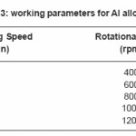
As it has mentioned earlier many parameters are introduced in FSW process, in the present work the parameters (factors) were considered, i.e. the welding speed, and the rotational speed with five levels for each factor and three replicates for each one. So that the process is carried out 75 times2 .Factors levels are being selected by trial and error to fix the working range for these levels in order to get defect free welds, table 2.3 shown the working range for the two factors, welding speed and rotational speed.
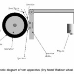
After fabricated the joints, Abrasion wear test was carried out based on ASTM G65-00 standard using the Dry Sand/Rubber Wheel Apparatus (see figure 2.4). The 25mm wide and 75mm in length abrasive wear resistance test specimens were cut from the middle area of the welded joints. The mass of all specimens were to the nearest 0.0001g as required by ASTM G65-00. The applied pressing force the test coupon against the wheel was TL = 130 [N] (test load – TL).
After the abrasive wear resistance test, the test Specimen was weighed at weight sensitivity 0, 0001 [g]. Mass loss of the Specimens were determined.12
Table 2.3: working parameters for Al alloy joints
Figure 2.4: Schematic diagram of test apparatus (Dry Sand/ Rubber wheel abrasion wear)
Results and Discussion
Abrasive wear test carried out for the specimens prepared from the stir-zone of the welded materials at different welding and rotational speed. The mass of specimen weighed before and after the test.
Effect of Welding Speed on Abrasive Wear Resistance
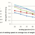
Figure 3.1 reveals the effect of welding speed on wear resistance. It is shown that abrasion wear resistance increased as the welding speed increased. At lower welding speed 22 mm/min the abrasion wear resistance was lower. When the welding speed was increased from 22 mm/min, the abrasion wear resistance was increased and reached a maximum at 101mm/min. This was found due to the hardening of the material caused by the lower heat input associated with faster welding speed.
Figure 3.1: Effect of welding speed on average loss of weight due to wear
Effect of Rotational Speed on Abrasive Wear Resistance
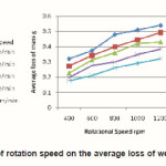
Figure 3.2 shows the effect of rotational speed on abrasion wear resistance of the joints. At lower rotational speed 400rpm, the abrasion wear resistance of the joints was higher. When the rotational speed was increased from 400 rpm, abrasion wear resistance was decreased and reaches a minimum at 1200 rpm this could be attributed to softening of material caused by higher heat input.
Figure 3.2: Effect of rotation speed on the average loss of weight due to wear
Analysis of Variance of Abrasive Wear Test Result
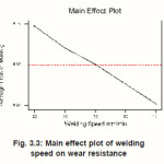
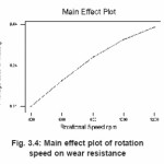
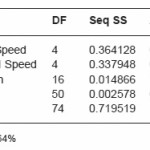
Figures 3.3 and 3.4 shows the main effect plot of welding speed and rotational speed respectively and indicates that the wear resistance increased with increasing welding speed and decreasing rotational speed. Also it can be concluded from table 3.1 that those two factors are the main effecting factors on wear resistance since they explain 99.64% variability in the model It’s clear from the table that welding speed has the largest sum of square 0.364128 so it can be inferred that welding speed has more significant effect on wear resistance followed by the rotational speed which is less significant.
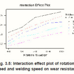
Figure 3.5 shows the interaction effect plot of rotational speed and welding speed on wear resistance, it can be concluded from the existence of parallels between the lines that the interaction effect of welding speed and rotational speed is not significant which support the result from table 3.1.
Figure 3.3: Main effect plot of welding speed on wear resistance
Figure 3.4: Main effect plot of rotation speed on wear resistance
Table 3.1: ANOVA of wear resistance
Figure 3.5: Interaction effect plot of rotational speed and welding speed on wear resistance
Conclusion
Abrasion wear resistance of the aluminum welded joints increased with decreasing rotational and it increased with increasing welding speed, because of hardening happened in metal due to grain size reduction associate with lower heat input per unit length.
Effectiveness of FSW process depends mainly on two factors temperature and thermal exposure which are controlled by two competitive processes: heat generation and heat dissipation. The heat generation is mainly determined by the tools rotational speed. Increasing rotational speed result in increased frictional heat, the heat dissipation is mainly controlled by welding speed. Increasing welding speed increases heat dissipation rate because the heated FSW zone is quickly cooled, after the welding tool passes it, during the welding process resulting in reduced temperature and duration of thermal exposure.
ANOVA indicates that welding speed is the dominant factor in the experiment, and interaction effect of rotational speed and welding speed is not significant.
The optimal processing parameter’s in the working range to achieve higher abrasion wear resistance is 400 rpm, 101 mm/min.
Acknowledgements
The authors are grateful to the Departments of mechanical engineering, Al-Balqa’ Applied University for extending the facilities of Workshop and Material Testing Laboratory to carry out this investigation.
References
- ASM Metals Hand book, Properties and Selection: Nonferrous Alloys and Special-Purpose Materials..
- K. Elangovan,V. Balasubramanian, S. Babu. Predicting tensile strength of friction stir welded AA6061 aluminium alloy joints by a mathematical model. Materials and Design 30: 188–193 (2009).
CrossRef
- R.S. Mishra, Z.Y. Ma. Friction stir welding and processing. Materials Science and Engineering R 50: 1-78 (2005).
CrossRef
- S.R. Ren, Z.Y. Ma and L.Q. Chen. Effect of welding parameters on tensile properties and fracture behavior of friction stir welded Al– Mg–Si alloy. Scripta Materialia 56: 69–72 (2007).
CrossRef
- R.M. Leal, C. Leit, A. Loureiroa, D.M. Rodriguesa, P. Vilac. Material flow in heterogeneous friction stir welding of thin aluminium sheets: Effect of shoulder geometry. Materials Science and Engineering A498: 384-391 (2008).
CrossRef
- V. Balasubramanian. Relationship between base metal properties and friction stir welding process parameters. Centre for Materials Joining Research. (CEMAJOR),Department of Manufacturing Engineering (2007).
- K.H. Zum Gahr, Microstructure and Wear of Materials. Tribology Series vol. 10, Elsevier, Amsterdam, 560 (1987).
- M. Moshgbar, R.R. Bearman, R. Parkin, Optimum control of cone crusher utilizing an adaptive strategy for wear compensation, Miner. Eng. 8(4-5): 367-376 (1995).
CrossRef
- C.M. Evertsson, Modelling of flow in cone crushers, Miner. Eng. 12: 1479-1499 (1999).
CrossRef
- K. Elangovan and V. Balasubramanian. Influences of tool pin profile and tool shoulder diameter on the formation of friction stir processing zone in AA6061 aluminum alloy.Center for materials joining research, (2007).
- ASM Material Hand Book. Metallography and Microstructure
- A. Klimpel, T. Kik, Erosion and abrasion wear resistance of GMA wire surfaced nanostructural deposits, Welding Department, Silesian University of Technology, (2008).

This work is licensed under a Creative Commons Attribution 4.0 International License.