Prashant Baredar, Jitendra Kumar*, Anil Kumar and Shankar Kumar
1Energy Department, MANIT, Bhopal, India.
2Department Mech. Engg., NIIST, Bhopal, India.
3Department Mech. Engg., LNCT, Bhopal, India.
DOI : http://dx.doi.org/10.13005/msri/080109
Article Publishing History
Article Received on : 01 Jan 2011
Article Accepted on : 18 Feb 2011
Article Published :
Plagiarism Check: No
Article Metrics
ABSTRACT:
In this study finite element analyses of rod extrusion process are carried out considering various processing parameters. The objective is to study the effect of these parameter on mechanical properties. Eighty one cases are simulated and corresponding stress; plastic strain and load distribution are critically examined. Based on these results, salient conclusions are drawn.
KEYWORDS:
Extrusion; Finite element analysis; Die angle; Stress; Hardening exponent
Copy the following to cite this article:
Baredar P, Kumar J, Kumar A, Kumar S. Effects of the Extrusion Process Parameter. Mat.Sci.Res.India;8(1)
|
Introduction
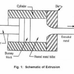
Extrusion is an important Metal forming operation. It is a manufacturing process used to create long objects of a fixed cross sectional profile. The extrusion process is based on the plastic deformation of a material due to compressive and shears forces only. No tensile forces are applied to the extruded metal. The latter allows the material to withstand high deformation without tearing out the material. Basically, this procedure is based on the reducing and shaping the cross section of piece of metal squeezing the material through an orifice or a die. Typically the blocks of metal used for this procedure are long straight parts with circular cross sections.
The extrusion of metals is used for the minimized need of extra finishing tasks the parts need after production; extruded Parts usually have a constant cross-section along its span
An analysis done by Kang,1 of three dimensional hot extrusion processes through landless square die is carried out as a non steady state problem. In the problem, difficulties arise from the severe distribution and die interference of elements at the aperture rim of the die, even with a small punch travel. Finite element simulation is impossible withought intermittent remeshing procedures. To overcome these difficulties, an automatic remeshing technique is proposed by employing a modular conceptual mesh structure. Venkata et. al 2 carried out a comprehensive investigation of an axisymetric steady state tube extrusion through a streamlined die is carried out by the FEM to study the influence of process variable on tool design and final product quality for a strain hardening material. The process variable considered is: The reduction in area, coefficient of friction, mandrel radius, dies length, the hardening capacity of material. The extrusion parameter studied is: the extrusion pressure, die pressure, mandrel pressure, hydrostatic stress distribution, strain rate distribution, strain distribution. Hur et.al.,3 carried out an analysis for the dimensional accuracy of the cold forged products that is strongly dependent on the elastic characteristics of the die.
Gouveia et.al.,4 carried out the finite element modeling of cold formed extrusion. Simulating metal forming processes using an updated larangian finite element formulation is not ideal when steady state material flow conditions prevail. Firstly, repeated calculation of large non linear finite element system are needed for continuously updating the mesh and secondary remeshing operations must be undertaken to avoid excessive mesh distortion and to introduce localized refinements in regions where large gradients are likely to occur.
Cosenza et.al.,5 carried out the damage and fracture study of cold extrusion dies. In this, die fracture in cold extrusion was investigated considering a few different die reduction zone geometries.
Peng et.al.,6 carried out the finite element analysis of spring back and secondary yielding effect during forward extrusion. The response of work material during forward extrusion and the subsequent unloading process was analyzed with a view to examining difficulties in prediction of component form errors, when different consecutive models are used.
Geometrical, Material & Frictional Parameters
Following geometrical, material and frictional parameters are considered in the study –
Geometrical Properties
Geometrical Properties
Billet diameter = 80 mm
Billet Length = 60 mm
Extruded Rod Diameter = 40 mm
Half Die angle = 300, 450 and 600
In this way, extrusion ratio comes out to be 4.
Material Properties
Billet is modeled as rigid material. Power law equation has been used for the modeling the stress strain behavior:

Where n is strain hardening exponent and K is strength coefficient.
Following values of material parameters are accounted-
Young’s Modulus = 78000
MPa Poison’s ratio = 0.33
Strength coefficient = 500, 600 and 700 MPa
Strain hardening exponent n = 0.1, 0.15 and 0.2
Friction
Coulomb friction criteria have been taken into the account for contact modeling. Three values of Coulomb friction coefficient viz 0.1, 0.15 and 0.2 are taken into the account.
FE Modeling and Boundary Conditions
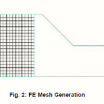
Finite Element Modeling of the rod extrusion process is carried out using MSC. Marc preprocessor. Die and punch are modeled as rigid and billet is modeled as deformable bodies. Axis symmetric finite element modeling is carried out using 4 nodes quadrilateral elements. Typical FE model is shown in Fig.2. There are 600 element and 651 nodes in the model. Displacement boundary condition is applied on the ram. Interaction of billet and die is accounted through contact algorithms of the software. Finite element simulation is carried out in incremental manner in 50 steps. Ram is given a displacement of 20 mm. Simulation results for the three dies, considering different strength factor, can be critically examined as below.
Results and Discussion
Effective Stress Distribution
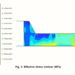
A typical stress contour in the extruded rod is shown in Fig. 3. It can be observed that quite large stress appears in the extrusion process.
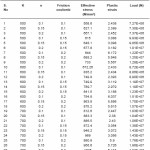
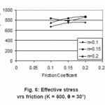
First of all keeping K=500 MPa, we vary the Die angle as 30°, 45° and 60° as shown in Table1, table2 and table3. We observe that as friction coefficient increases the value of effective stress increases with increasing value of Hardening Exponent. As the Die angle increases the slope of curve decreases.
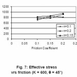
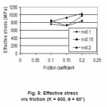
Again for K = 600 and 700, we plot the graph considering the angle 30°, 45° and 60° one by one. And a close study is done by plotting graph how the Effective stress varies when other parameters are varies.
Plastic strain distribution
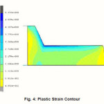
A typical plastic strain contour is shown in Fig. 4. It can be observed that strain can be as high as 7.
Total plastic strain distribution for all the cases are given in table 4, table 5 and table 6. Plastic strain has been studied under the different condition of frictional coefficient, Die angle, Strength Factor and hardening Exponent.
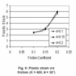
For K = 500 and θ = 30°, 45° and 60° the value of frictional coefficient increases plastic strain also increases or from increasing value of Hardening exponent slope of curve increases. For higher value of Die angle slope of plastic strain changes from minimum to maximum.
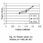
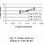
For K = 600 and Die angle 30° for all value of n, strain increases with increasing value of µ.for 45° and 60° slope reduces with n and increasing value of µ.
As die angle increases plastic strain increases for constant value of strength factor as observed in table. While for constant die angle the strength factor increases slope increases, but for increasing value of die angle slope of Plastic Strain decreases as observed. With increasing value of hardening exponent plastic strain increases.
Table 1: Stress, strain & load for 30º Die
Load Distribution
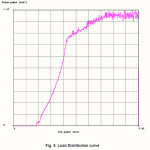
A typical load curve of the extruded rod is shown in Fig.5. It can be observed that quite large load appears in the extrusion process.
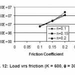
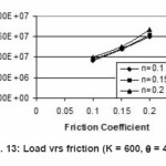
The applied load on billet depends on various parameters like frictional coefficient, strength factor, Hardening exponent and die angle. In all these frictional force plays most important role. As friction increases the work load increases and thus applied Load. Since friction occurs only at the surface and throughout the thickness of metal billet. It introduces microscopic inhomogenity, resulting in micro cracks on surface and weaker products having lower fatigue strength.
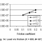
Variation of Load distribution with the variation of frictional Coefficient has been shown from Fig 13 to Fig. 14, changing with various parameters.
For K = 500, we vary angle and observe that the load curve slope increases with the increases in value of hardening exponent. In case die angle 60º initially load increases but after a certain value of friction coefficient load decreases with increasing value of hardening exponent.
Again for K = 600 and 700, we plot the graph considering the angle 30º, 45 º and 60 º one by one. And a close study is done by plotting graph how the Effective stress varies when other parameters are varies.
In the same way when angle die are constant and strength factor increases then it goes towards constant and the load is most affected by friction coefficient. As friction coefficient increases, load increases, it is desirable to keep the load requirement as low as possible.
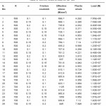
Table 2: Stress, strain & load for 45° Die
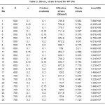
Table 3: Stress, strain & load for 60º Die
Figure 1: Schematic of Extrusion
Figure 2: FE Mesh Generation
Figure 3: Effective stress contour (MPa)
Figure 4: Plastic Strain Contour
Figure 5: Load Distribution curve
Figure 6: Effective stress vrs friction (K = 600, θ = 30°)
Figure 7: Effective stress vrs friction (K = 600, θ = 45°)
Figure 8: Effective stress vrs friction (K = 600, θ = 60°)
Figure 9: Plastic strain vrs friction (K = 600, θ = 30°)
Figure 10: Plastic strain vrs friction (K = 600, θ= 45°)
Figure 11: Plastic strain vrs friction (K = 600, θ= 60°)
Figure 12: Load vrs friction (K = 600, θ = 30°)
Figure 13: Load vrs friction (K = 600, θ = 45°)
Figure 14: Load vrs friction (K = 600, θ= 60°)
Conclusions
In this study effects of processing parameters on rod extrusion are studied using FEM 81 cases considering various geometrical, material and friction parameters are simulated.
For constant die angle, stresses are proportional and inversely proportional to hardening exponent and strength coefficient respectively
Stress decreases with increase in die angle.
Plastic strain decreases with increase in strain hardening exponent.
Plastic strain decreases with the increasing value of Die angle.
Plastic strain increases with increasing value of strength Factor.
Load increases with the increasing value of strain hardening Exponent.
Load decreases with increasing value of strength factor.
Load increases with increasing value of Die angle.
References
- Kang Y.S. and Yang Y. D., A Three-Dimensional Rigid-Viscoplastic Finite Element Analysis of Isothermal Square Die Extrusion of a Square Section Based on ALE Description.volume 5, Number 1 (1996).
- Venkata Reddy N., Dixit P M. and Lal, G.K.,Die design for axisymmetric hot extrusion,Int. J. Math. Tools Manufact., 37(11): 1635-1650 (1997).
CrossRef
- Hur K.D, Yeo H.T, Choi Y, Analysis and design of the Prestressed cold extrusion die, Int. J. Adv. Manuf. Technol. 18: 54-61 (2001).
CrossRef
- Gouveia B. P. P. A., Rodrigues J. M. C., Bay N., Martins P. A. F., Finite-element modelling of cold forward extrusion, Journal of Materials Processing Technology, 94(2-3): 85-93 (1999).
CrossRef
- Cosenza C, Fratini L, Pasta A. and Micari F:Engineering fracture mechanics, 71(7):1041-1053(13) (2004).
- Peng X, Qin Y and Balendra R: Journal ofmaterial processing technology, 135(2): 211-218(8) (2003).
- Dieter G.E, Mechanical Metallurgy, McGraw Hill (1988).
- Mehta V. Bhavin, Hamza Ghulman, Rick Gerth Extrusion Die Design: A New Methodology for Experimental Design as a Precursor to Neural Networks” JOM, 51(9) (1999).
- Chakraborti N., Genetic Algorithms is Material Design and Processing, International Material Reviews, 49(3-4): 246-260 (2004).
CrossRef
- Chung J S., and Hwang S.M, Application of genetic algorithm to the optimal design of the die shape in extrusion, Journal of Material Processing and Technology, 72: 69-77 (1997).
CrossRef
- Hong Yan, Juchen Xia, An approach to the optimal design of technological parameters in the profile extrusion process, Science and Technology of Advanced Materials, 7: 127-131 (2006).
CrossRef
- Hosford, W F; Caddell, R M Metal Forming: Mechanics and Metallurgy. Prentice-Hall (1983)
- Deb Kalyanmoy, Optimization for Engineering Design Algorithms and Examples, Prentice Hall of India Private Limited, New Delhi,1993
- Kim N H, Kang C G., Kim B M., Die design optimization for axisymmetric hot extrusion of metal matrix composites, International Journal of Mechanical Sciences 43: 1507-1520 (2001).
CrossRef
- Narayanasamy R, Srinivasan P and Venkatesan R., Computer aided design and manufacture of streamlined extrusion dies, Journal of Materials Processing Technology, 138(1-3): 262-264 (2003).
CrossRef
- Poursina M., Parvizian J. and Antonio C.A.C., Optimum pre-form dies in two-stage forging, Journal of Materials Processing Technology, 174(1-3): 325-333 (2006).
CrossRef
- Srinivasan N., Ramakrishnan N., Venugopal Rao A. and Swamy N.,CAE for forging of titanium alloy aero-engine disc and integration with CAD–CAM for fabrication of the dies, Journal of Materials Processing Technology, 124(3) (2002).
CrossRef
- User’s Manual MSC.Superforge software (2005).

This work is licensed under a Creative Commons Attribution 4.0 International License.