C. Sivakandhan1* and P. Suresh Prabhu2
1*Department of Mechanical, Karpagam University, Coimbatore, India.
2Department of Mechanical, United Institute of Technology, Coimbatore, India.
DOI : http://dx.doi.org/10.13005/msri/080118
Article Publishing History
Article Received on : 27 Apr 2011
Article Accepted on : 07 Jun 2011
Article Published :
Plagiarism Check: No
Article Metrics
ABSTRACT:
In this work an attempt has been made for design optimization of composite drive shafts for power transmission applications. The one-piece composite drive shaft is designed to replace conventional steel drive shaft of an automobile using E-glass/epoxy and high modulus carbon/epoxy composites. A solution technique using ansys for design optimization of composites drive shafts is presented here. The purpose of using ansys to minimize the weight of shaft that is subjected to the constrains such as torque transmission. The weight savings of the E-glass/epoxy and corbon/epoxy shaft were 15%and 72%of the steel shaft respectively. Automotive drive Shaft is a very important component of vehicle. The present paper focuses on the design of such an automotive drive shaft by composite materials. Now a day's two pieces steel shaft are used as drive shaft. However the main advantages of the present design is; only one piece of composite drive shaft is possible that fulfill all the requirements of drive shaft. Two different designs are proposed one is purely from E-glass/epoxy and other is using Carbon/epoxy. The basic requirements considered here are torsional strength torsion buckling and bending natural frequency. An optimum design of the draft shaft is done which is cheapest and lightest but meets all of the above load requirements. Progressive failure analysis of the selected design is also done.
KEYWORDS:
E-glass; Composites; Ansys
Copy the following to cite this article:
Sivakandhan C, Prabhu P. S. Optimum Design and Analysis of the Drive Shaft in Composite Material. Mat.Sci.Res.India;8(1)
|
Introduction
Composite materials, often shortened to composites, are engineered or naturally occurring materials made from two or more constituent materials with significantly different physical or chemical properties which remain separate and distinct at the macroscopic or microscopic scale within the finished structure.
The theoretical details of composite materials and composite structures are extensively reviewed. The Spicer V-Joint Division of Dana Corporation for the Ford Econoline van models developed the first composite propeller shaft in 1985. The General Motors pickup trucks which adopted the Spicer product enjoyed a demand three times that of projected sales in its first year. John. W. Weeton et al. briefly described the application possibilities of composites in the field of automotive industry to manufacture composite elliptic springs drive shafts and leaf springs. Beard more and Johnson discussed the potential for composites in structural automotive applications from a structural point of view. Pollard studied the possibility of the polymer Matrix composites usage in driveline applications. Faust etal described the considerable interest on the part of both the helicopter and automobile industries in the development of lightweight drive shafts.
Procedure for finding the elastic moduli of anisotropic laminated composites is explained by Azzi.V.D etal. Azzi.V.D .etal discussed about anisotropic strength of composites.
Lateral Vibration
Vibration refers to mechanical oscillations about an equilibrium point. The oscillations may be periodic such as the motion of a pendulum or random such as the movement of a tire on a gravel road.
Bauchau developed procedure for optimum design of high-speed composite drive shaft made of laminates to increase the first natural frequency of the shaft and to decrease the bending stress. Shell theory based on the critical speed analyses of drive shafts has been presented by Dos Reis et al. Patricia L.Hetherington investigated the dynamic behaviour of supercritical composite drive shafts for helicopter applications. Ganapathi.et.al extensively studied the nonlinear free flexural vibrations of laminated circular cylindrical shells. A method of analysis involving Love’s first approximation theory and Ritz’s procedure is used to study the influence of boundary conditions and fiber orientation on the natural frequencies of thin orthotropic laminated cylindrical shells was presented. A first order theory was presented by Lee to detennine the natural frequencies of an orthotropic shell. Nowinski. J.L. investigated the nonlinear transverse vibrations of elastic orthotropic shells using Von-Karman-Tsien equations.
Optimisation
The optimum design of laminated plates and shells subjected to constraints on strength stiffness buckling loads and fundamental natural frequencies were examined. Methods were proposed for the determination of the optimal ply angle variation through the thickness of symmetric angle-ply shells of uniform thickness. The main features of GAs and several ways in which they can solve difficult design problems were discussed by Gabor Renner et.a1. Raphael T.Haftka discussed extensively about stacking-sequence optimization for buckling of laminated plates by integer programming. The use of a GA to optimize the stacking sequence of composite laminates for buckling load maximization was studied. Various genetic parameters including the population size the probability of mutation and the probability of crossover were optimized by numerical experiments. The use of GAs for the optimal design of symmetric composite laminates subject to various loading and boundary conditions were explained. Kim et.al.
Minimized the weight of composite laminates with ply drop under a strength constraint. The working of Simple Genetic Algorithm was explained by Goldberg. Rajeev and Krishnamoorthy proposed a method for converting a constrained optimization problem into an unconstrained optimization problem.
Scheme 1:
Scheme 2:
Scheme 3:
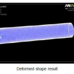
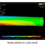
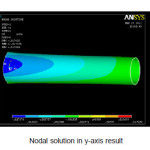
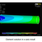
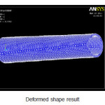
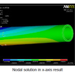
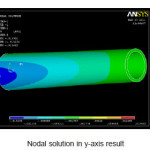
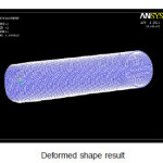
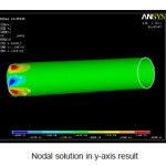
Analysis Result for Existing Shaft
Scheme 4:
Scheme 5:
Scheme 6:
Scheme 7:
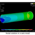
Analysis Result for Composite Material for E- Glass Fiber
Scheme 8:
Scheme 9:
Scheme 10:
Scheme 11:
Scheme 12:
Scheme 13:
Factor of Safety
Factor of safety is a term describing the structural capacity of a system beyond the expected loads or actual loads. Essentially, how much stronger the system is than it usually needs to be for an intended load. Safety factors are often calculated using detailed analysis because comprehensive testing is impractical on many projects, such as bridges and buildings, but the structure’s ability to carry load must be determined to a reasonable accuracy.
The designer must take into account the factor of safety when designing a structure. Since composites are highly orthotropic and their fractures were not fully studied the factor of safety was taken as 2.
Function of the Drive Shaft
First it must transmit torque from the transmission to the differential gear box.
During the operation it is necessary to transmit maximum low-gear torque developed by the engine.
The drive shafts must also be capable of rotating at the very fast speeds required by the vehicle.
The drive shaft must also operate through constantly changing angles between the transmissions the differential and the axles. As the rear wheels roll over bumps in the road the differential and axles move up and down. This movement changes the angle between the transmission and the differential.
The length of the drive shaft must also be capable of changing while transmitting torque. Length changes are caused by axle movement due to torque reaction road deflections braking loads and so on. A slip joint is used to compensate for this motion. The slip joint is usually made of an internal and external spline. It is located on the front end of the drive shaft and is connected to the transmission.
Overall Shaft Torque Averages for Each Flex
One of the most obvious points that can be seen from comparing a list of torque measurements from the Dynacraft/Apollo test to the manufacturers’ own published ratings is that no company publishes torque measurements for their steel shafts. This is an interesting point which underscores the fact that torque in a steel shaft has to be considered an entirely different parameter than it is in a graphite shaft. The main reason shaft manufacturers do not publish torque measurements for steel shafts is that torque does not vary from high to low nearly as much as it does in a graphite shaft.
When a steel shaft is designed once the weight wall thickness step pattern length and the shaft’s various diameters are set the torque cannot be changed to any significant degree. Because the shaft is homogenous in its nature i.e. made from the same material throughout torque in a steel shaft is essentially a product of the geometric specifications of the shaft. To contrast in a graphite shaft once the manufacturer defines all of the geometric specifications of the shaft the torque can still be altered significantly. By varying the strength of the composite material and changing both the number of layers and the orientation of the various layers are aligned to the axis of the shaft a graphite shaft manufacturer has the ability to control the torque independently of the shaft’s other specifications. To first understand about torque one must know that steel shaft do indeed have torque. Next how does torque in steel shafts compare to that of graphite shaft? provides the torque average of current model shafts at the time of this second.
Specification of the Problem
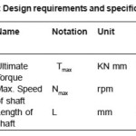
The fundamental natural bending frequency for passenger cars small trucks and vans of the propeller shaft should be higher than 6500 rpm to avoid whirling vibration and the torque transmission capability of the drive shaft should be larger than 3500 Nm. The drive shaft outer diameter should not exceed 100 mm due to space limitations. Here outer diameter of the shaft is taken as 90 mm. The drive shaft of transmission system is to be designed optimally for following specified design requirements as shown in Table.
Steel (SM45C) used for automotive drive shaft applications. The material properties of the steel (SM45C) are given in Table. The steel drive shaft should satisfy three design specifications such as torque transmission capability buckling torque capability and bending natural frequency.
Table 1: Design requirements and specifications
Assumption
The shaft rotates at a constant speed about its longitudinal axis.
The shaft has a uniform circular cross section.
The shaft is perfectly balanced i.e. at every cross section the mass center coincides with the geometric center.
All damping and nonlinear effects are excluded.
The stress-strain relationship for composite material is linear & elastic; hence Hooke’s law is applicable for composite materials.
Acoustical fluid interactions are neglected i.e. the shaft is assumed to be acting in a vacuum.
Since lamina is thin and no out-of-plane loads are applied it is considered as under the plane stress.
Selection of Cross Section
The drive shaft can be solid circular or hollow circular. Here hollow circular cross-section was chosen because:
The hollow circular shafts are stronger in per kg weight than solid circular.
The stress distribution in case of solid shaft is zero at the center and maximum at the outer surface while in hollow shaft stress variation is smaller. In solid shafts the material close to the center are not fully utilized.
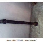
Test Report for Existing Shaft
Geometry of drive shaft
Shaft length – 500mm
Shaft diameter – 51mm
Thick of shaft – 1.75mm
This is for light motor vehicles (Omni)
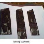
Test Result for Chemical Composition
For nature of sample- sheet from propeller shaftautomobile
sample:
1.75mm × 35mm × 300mm
Elements – %by weight
Carbon – 0.234
Silicon – 0.210
Manganese – 0.850
Sulphur – 0.030
Phosphorous – 0.040
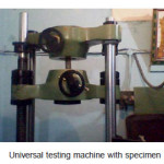
Test result for mechanical properties
Tensile strength – 734MPa
Stress proof – 496MPa
% Elongation – 10% (Length on 100mm)
Hardness – 219-229BHN
Conclusion
A procedure to design a composite drive shaft is suggested. Drive shaft made up of E-glass/ epoxy and corbon/epoxy multilayered composites have been designed. The designed drive shafts are optimized using ansys better torque transmission capacity and bending vibration characteristics. The usage of composite materials and optimization techniques has resulted in considerable amount of weight saving in the range of15%to72%when compared to conventional steel shaft. These results are encouraging and suggest that ansys can be used effectively and efficiently in other complex and realistic designs often en countered in engineering applications.
References
- Pilato, L.; and Michno, Michael J., (Chap 1 Introduction, and Chapter 2 “Matrix Resins”). Advanced composite materials. Springer-Verlag New York (1994).
- OSHA, “Polymer Matrix Materials: Advanced Composites”. U.S. Department of Labor. Retrieved 2010-06-05. Public domain content from a U.S. government department (2009).
- ACG (Copyright 2006). “Introduction to Advanced Composites and Prepreg Technology”
- Dwayne A., “Composites and Advanced Materials” (Centennial of Flight Commemoration Act Public Law 105-389 105th Congress (November 13, 1998)). NASA. U.S. Centenial of Flight Commission. (2003).
- J. N. Reddy, An Introduction to the Finite Element Method, 3rd ed., McGraw-Hill Education (2005).
- J. N. Reddy, Mechanics of Laminated Composite Plates and Shells: Theory and Analysis, 2nd Ed.
- Mallick,p.k fiber reinforced composites marcel decker (1988),
- Rao, S.S. Mechanical Vibrations. Addision-wesely publishing company.
- Vijayaragavan,S, Rajendran .i Optimal design of a composite leaf spring using genetic algorithm computers and structures
- Mallick, P Newman, K. composite materials tech. hanser publishers inc (1990)

This work is licensed under a Creative Commons Attribution 4.0 International License.