Simulation Studies on Structural Behaviour of Single-Walled Carbon Nanotubes - Using Finite Element Analysis Technique
Ratnakar Pandu1*, Chidanandappa2 and N. C. S. Reddy3
1Department of Mechanical Engineering, M.J. College of Engineering and Technology, Banjara Hills, Hyderabad - 32, India.
2NRSA, Balanagar, Hyderabad, India.
3Department of Mechanical Engineering, CMR Group of Institutions Secunderabad. A.P, India.
DOI : http://dx.doi.org/10.13005/msri/080125
Article Publishing History
Article Received on : 10 Apr 2011
Article Accepted on : 21 May 2011
Article Published :
Plagiarism Check: No
Article Metrics
ABSTRACT:
In this present paper, an FE approach has been presented for the elastic bending and buckling behaviors of single-walled carbon nanotubes (SWCNTs). Finite element simulations are carried out to investigate the bending deformations and buckling behaviors of SWCNTs under various conditions. Both axial compression and bending loading conditions are considered. The computed results for SWCNTs agree well with atomistic simulations in the literature and the FE approach is confirmed successfully. In this paper, the steady state structural analysis has been performed to know the strength of the CNTs using shell93 element. For analysis of SWCNT has been considered as cantilever beam and loaded at the free end. SWCNTs with different lengths, different thicknesses under various materials and loadings have been studied. In static analysis, the defections and stress induced are estimated due to axial and bending loads. Under buckling analysis, the buckling factors and corresponding mode shapes are plotted. The displacement response is plotted and reported.
KEYWORDS:
Shell93 element; SWCNTs; Finite element analysis; cantilever bukling analysis
Copy the following to cite this article:
Pandu R, Chidanandappa, Reddy N. C. S. Simulation Studies on Structural Behaviour of Single-Walled Carbon Nanotubes - Using Finite Element Analysis Technique. Mat.Sci.Res.India;8(1)
|
Copy the following to cite this URL:
Pandu R, Chidanandappa, Reddy N. C. S. Simulation Studies on Structural Behaviour of Single-Walled Carbon Nanotubes - Using Finite Element Analysis Technique. Mat.Sci.Res.India;8(1). Available from: http://www.materialsciencejournal.org/?p=2572
|
Introduction
From the day of discovery of carbon nanotube (CNT) by Iijima1, many researchers have been attracted to this material and large numbers of papers have been published in this area. CNT was first synthesized as a by-product in arc-discharge method in synthesis of fullerenes and currently being prepared by different methods2,3. In this work, keeping the application of CNT in mind, an attempt is made to apply Finite element (FE) method for the elastic bending and buckling behaviours of single-walled carbon nanotubes (SWCNTs). CNTs can be classified into two types:
(1) Multi-walled CNT (MWCNT)1, 2 and (2) Single-walled CNT (SWCNT).3 The MWCNTs had been discovered earlier than SWCNTs. The MWCNT is comprised of 2 to 30 concentric graphitic layers, diameters of which range from 10 to 50 nm and length which range from 100 to several 100s of nm. On the other hand, SWCNT is much thinner with the diameters from 0.34 to 1.4 nm. Carbon nanotubes are very strong4,5 and superior in performance when compared to other conventional materials such as aluminum, tungsten carbide, steel, and other alloys of carbon and aluminum. Carbon nanotubes exhibit superior mechanical, electrical, optical, and thermal properties which other materials cannot exhibit. A lot of research is going on to know the behavior of carbon nanotubes under various conditions such as bending, buckling, twisting etc.6 Different scientists and researchers have used various methods such as Molecular Dynamics, Van dar Waal equations and Finite Element Method7 for finding the properties of carbon nanotubes.
As the geometry of the carbon nanotube is in nano scale, it would be difficult to handle the model when performing analysis. It requires special tools and set ups such as Transmission Electron Microscopy (TEM), Automic Force Microscopy (AFM), Scanning Electron Microscopy (SEM), computer controlled environment, and experienced persons to carryout the experiment. So one would require a tool which can be used for analysis without any set ups (like TEM, AFM, SEM) and give results as accurate as the actual experiment would. Finite Element Analysis (FEA) is a tool which can fulfill the above requirement with ease. In this work, an attempt is made to implement an FE approach for the elastic bending and buckling behaviors of single-walled carbon nanotubes (SWCNTs). Finite element simulations are carried out to investigate the bending deformations and buckling behaviors of SWCNTs under various conditions. Both axial compression and bending loading conditions has been considered.
Structural Analysis of Swcnts
In this paper, ANSYS 10.0 which is an FEA tool is adopted to model and to carryout analysis on carbon nanotubes. ANSYS 10.08 is one of the best tools which give accurate results in less time.
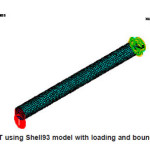
Figure 1: SWCNT using Shell93 model with loading and boundary conditions
The Geometry and Material Properties of the SWCNT for Modeling
As dimensions of the model are very small even a small amount of error is not permitted. To build the model accurately Shell 93 element is used. The inner and outer diameters of the tube are 0.34nm and 1.02nm respectively, thickness of tube wall is 0.34 nm, length of the tube is 8nm,Young’s modulus is 4.84TPa,7 Poisson’s ratio is taken as 0.2, density is 1400 kg/m3 and an assumed load is 10 nN. In this work, the carbon nanotube is assumed as a cantilever beam. The beam is modeled using a shell element (SHELL 93). The shell93 element has six degrees of freedom at each node (3 translational and 3 rotational in x, y, z-axes). In this model the tube is fixed at one end and the load is applied at the free end. Constraints given at fixed end are all degrees of freedom are fixed i.e. displacements and rotations in x, y, z-axes are zero (UX = UY = UZ = ROTX = ROTY = ROTZ = 0) and the other end is free.
Structural Analysis Studies
Two cases have been considered for analyses of CNTs. In each case, properties of the nanotubes are altered and the results were studied. In case1, the bending behavior of SWCNTs by varying thickness and length are studied and in case2, the buckling behavior of SWCNTs by varying thickness and length were studied and obtained the corresponding mode shapes.
Bending Behavior of Swcnts
In this section, two conditions again are taken into consideration for studying bending behavior of nanotube by varying the geometry, (a) Bending behavior of single-walled carbon nanotube by varying the thickness and (b) Bending behavior of single-walled carbon nanotube by varying the length.
Bending Behavior of Single-Walled Carbon Nanotube by Varying the Thickness
In this first condition, thickness of the tube is changed keeping inner diameter, length, and load constant. The geometry and the material properties taken for analysis are: Inner diameter=0.34 nm, Length of tube=8 nm, Modulus of elasticity= 4.84TPa,7 Poisson’s ratio considered as 0.2, assumed bending load is 10 nN, and thicknesses considered as 0.34, 0.39, 0.44, 0.49, 0.54 (nm). Under each thickness of the CNT, a comparison is made for the bending stress and a graph is ploted for length of CNT against the deformation.
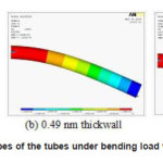
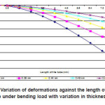
From the fig.3, it is observed that the carbon nanotube with more wallthickness the induced deformation less though the inner diameter of all the tubes is same. With this it can be concluded that the deformation of the tube is inversely proportional to its thickness. So if the thickness of the tube increases then the load carrying capacity of the tube also increases and it is self reinforced. Similarly, we compared Von Mises stress for different tube thicknesses and ploted graph.
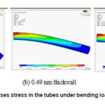
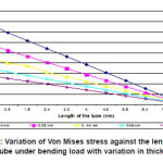
From the fig.5, it can be observed that the induced Von Mises stress is more in the tube having less thickness and is less in the tube having more thickness. There fore the stress induced in the tube is inversely proportional to the thickness of the tube.
Figure 2(a-c): Deformed shapes of the tubes under bending load with different thicknesses
Figure 3: Variation of deformations against the length of the tube under bending load with variation in thickness
Figure 4(a-c): Variation of Von Mises stress in the tubes under bending load with different thicknesses
Figure 5: Variation of Von Mises stress against the length of the tube under bending load with variation in thickness
Bending Behavior of Single-Walled Carbon Nanotube by Varying the Length
In this case, length of the tube is changed by keeping thickness, inner diameter, outer diameter, and load constant. The length of the tube is changed to 8 nm, 10 nm, 12 nm, 15 nm, and 20nm. As the length of the tube is not constant only first 8 nm of length from the fixed end is considered for the analysis. The properties and the geometry of CNT are: Inner diameter=0.34 nm, Outer diameter=1.02 nm, Thickness of NT=0.34nm, Modulus of elasticity=4.84 TPa, Poisson’s Ratio=0.2, Assumed bending load=10 nN, and Lengths = 8, 10, 12, 15, 20 (nm).
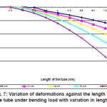
From the fig.7, it can be observed that the deformation in the tube having greater length is more though the properties of all the tubes are same. The tube which is short in length deforms less. With this it is clear that the deformation in the tube is proportional to the length of the tube.
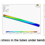
From the fig.8, it can be observed that the induced Von Mises stress in the tube having maximum length is more. So with this it is clear that the stress distribution is proportional to the length of the tube.
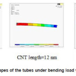
Figure 6: Deformed shapes of the tubes under bending load with different lengths
Figure 7: Variation of deformations against the length of the tube under bending load with variation in leng
Figure 8: Variation of Von Mises stress in the tubes under bending load with different lengths
Buckling Behavior of Swcnts
In this case, two conditions are taken into consideration for studying the bending behavior of nanotube by varying the geometry, (a) Buckling behavior of single-walled carbon nanotube by varying the thickness. (b) Buckling behavior of single-walled carbon nanotube by varying the length.
Buckling Behavior of Single-Walled Carbon Nanotube by Varying the Thickness
In this case thickness of the tube is changed keeping inner diameter, length, and load constant. There are five thicknesses considered whose values are 0.34 nm, 0.39 nm, 0.44 nm, 0.49 nm and 0.54 nm. The geometry and the material properties taken for analysis are: Inner diameter=0.34nm, Length of NT = 8nm Modulus of elasticity=4.84TPa, Poisson’s ratio=0.2, Load=10nN(compressive) and Thickness=0.34, 0.39, 0.44, 0.49 and 0.54 (nm).
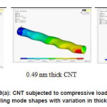
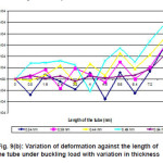
From the fig.9 (a-b), it can be observed that the tube having maximum thickness deforms less under the same buckling load. With this it can be concluded that the buckling behavior is inversely proportional to the thickness of the tube. A compressive force of 10nN (assumed) is applied on the tube to calculate the critical buckling load. It can be observed that the critical buckling load is higher for the tube having maximum thickness, from this it can be concluded that the critical buckling load is proportional to the thickness of the tube.
Figure 9(a): CNT subjected to compressive load and buckling mode shapes with variation in thickness
Figure 9(b): Variation of deformation against the length of the tube under buckling load with variation in thickness
Buckling Behavior of Single-Walled Carbon Nanotube by Varying the Length
In this case, length of the tube is changed by keeping thickness, inner diameter, outer diameter, and load constant. The length of the tube is changed to 8 nm, 10 nm, and 12 nm. As the length of the tube is not same, only first 8 nm of length from the fixed end is considered for the analysis. The properties of the tube and the geometry are: inner diameter=0.34 nm, outer diameter=1.02 nm, thickness of tube=0.34 nm, Modulus of elasticity=4.84 TPa, Poisson’s Ratio=0.2, Load=10 nN (compressive), Length =8, 10, 12, 15 and so on in nm.
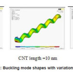
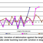
From the fig.10(a-b) it can be observed that the deformation and buckling is more in the tube having larger length. So the larger length tubes are not required where large amount of buckling is undesirable in nanotechnology applications. The long tube can be replaced by two small tubes joining one over the other. A compressive force of 10nN is applied on the tube to calculate the critical buckling load. It can be observed that the critical load of buckling is inversely proportional to the length of the tube. It is desirable to have shorter tubes where the tube is subjected to more compressive forces. The tube with lesser length will work effectively where the nano structures are subjected to buckling.
Figure 10(a): Buckling mode shapes with variation in length
Figure 10(b): Variation of deformation against the length of the tube under buckling load with variation in length
Conclusions
Structural analyses on the single-walled carbon nanotubes have been done and drawn the conclusions: (1)It is observed that the carbon nanotube with more thickness had deformed less though the inner diameter of all the tubes is same. From this, it can be concluded that the deformation of the tube is inversely proportional to its thickness. (2)The induced Von Mises stress is more in the tube having less thickness and is less in the tube having more thickness.(3)The deformation in the tube having greater length is more though the properties of all the tubes are same. (4)The tube which is short in length deforms less. This is because of the aspect ratio. Therefore, the deformation is proportional to the aspect ratio. (5)The induced Von Mises stress in the tube having maximum length is more. (6)The tube having maximum thickness deforms less under the same buckling load. (7)The critical load of buckling is higher for the tube having maximum thickness. (8) The deformation and buckling is more in the tube having larger length. (9)The critical load of buckling is inversely proportional to the length of the tube.
References
- Iijima, S., Nature, 354: 56 (1991).
CrossRef
- Zhao, X., Ohkohchi, M., Wang, M., Iijima,S., Ichihashi, T. and Ando, Y., Carbon, 35:775 (1997).
CrossRef
- Iijima, S. and Ichihashi, T., Nature, 363: 603(1993).
CrossRef
- Harris, P.J.F., Carbon Nanotubes and Related Structures, Cambridge University Press, Cambridge, UK (1999).
- Dresselhaus, M.S., Dresselhaus, G., Avouris, P., Carbon Nanotubes, Spinger, Heidelberg (2001).
- X.Guo, A.Y.T. Leung, X.Q. He, H. Jiang, Y.Huang., Bending buckling of single-walled carbon nanotubes by atomic-scale finite element, Composites: Part B 39: 202-208 (2008).
CrossRef
- Antonio Pantano, David M. Parks, Mary C.Boyce., Mechanics of deformation of singleand multi-wall carbon nanotubes, Journal of the Mechanics and Physics of Solids 52: 789-821 (2004).
CrossRef
- ANSYS, ANSYS Multiphysics users’ manual, Version Release 10.0.

This work is licensed under a Creative Commons Attribution 4.0 International License.