The goal of alignment technique is meet the standards. Standards are a means of scooping the work expected of technician. By precisely defining the results, standards are a means of controlling the cost to the level where the results are achieved and no more. Whether alignment is done in-house, or as a contracted service, the results should be consistently the same when the same standards are enforced.
But must know if shaft misalignment. Misaligned shafts will often cause problems with the components in the machinery. Investigations made in the USA have shown that misalignment can be traced as the cause of about 50% of the breakdown in rotating machinery. Organized and implemented alignment of the shafts therefore is a profitable form of preventative maintenance.1
The basic types of misalignments are parallel (offset) and angular. In practice these always occur in combination. The objective with shaft alignment is to adjust two units of rotating machinery so that the shafts of the units are in a straight line.
Having correctly aligned machines reduces the risk of breakdowns. There is much to be gained in terms of time and money by adjusting the machines within the prescribed tolerances. Investing in a laser-based measuring system and the working Environment is improved at the same time.1-2
Excessive axial and radial forces on the bearings, which reduce longer bearing life and rotor stability under dynamic operating conditions.
Increase shaft bending from the point of power transmission in the coupling to the coupling end bearing.
Increases wear in the coupling components.
Possibility of shaft failure from cyclic fatigue.
Possibility of increase vibration levels in machine casings, bearing housings, and rotors
Premature bearing, seal, shaft, or coupling failures
For a flexible coupling to accept both parallel and angular misalignment there must be at least two points where the coupling can ‘flex’ or give to accommodate the misalignment condition. The goal of the person doing the alignment is to position the machinery casings such that all of these deviations are below certain tolerance values. Therefore misalignment can be classify into four grades depend on the details from different manufacture including bearing manufacturers, coupling manufacturers, alignment system consultants and so on.
Unsafe: the degree of misalignment is outside the tolerance limit.
Poor: the degree of misalignment is inside the tolerance limit but outside the recommended limit.
Acceptable: the degree of misalignment is in the recommended range for operating.
Excellent: the degree of misalignment is close to perfect alignment.1-3
Alignment Standards
The purpose of this standard is to guarantee reliability of mechanical equipment when first placed into service and after major repair. It specifies the alignment condition of components to reduce vibration and minimize wear the purposes of this standard are given below.
The equipment is guaranteed for minimum dynamic forces and wear.
To detect grossly defective components, like bent shafts
This standard defines acceptable limits for shaft-to-shaft alignment of coupled machines. The limits are defined in terms of axial offset and radial offset.4,5
Many researches had been carried out to study the shafts alignments problem. Markrand, 2003, this study focused on Shaft alignment is a technical skill that is not common in the construction and maintenance professions, but categorized more like a specialty. It requires unique and expensive measurement instruments, some calculation capability, and relies heavily on experience for successful results on heavy, high-speed, or high-temperature machines. At present there are no universally accepted standards that define good results. This paper covers alignment standard for Four-dial indicator method. All these standards are developed only on experience basic which are useful for alignments in Thermal Power Station’s Coal Handling Plants. The goal of these standards is to provide the technician with the recommended approach for the quality alignment.1
Tan Liao,2008, The current study constructs a measurement system comprising a laser light source and a detector to facilitate the alignment of two rotating shafts. The alignment process is modeled and analyzed using a 4 × 4 homogeneous transformation matrix. The analysis commences by using the transformation matrix to trace the paths followed by the skew rays within the alignment system. Analytical formulae are then derived to enable the major misalignment parameters of the two shafts, namely the horizontal angularity, the horizontal offset, the vertical angularity and the vertical offset, to be inversely extracted from the detector readings such that the two shafts can be correctly aligned. The validity of the proposed approach is confirmed by performing a series of experimental alignment trials for various initial misalignment conditions.²
Shiyu Zhou and Jianjun Shi (2001) made a review of the research work performed in real-time active balancing and active vibration control for rotating machinery, as well as the research worked on dynamic modeling and analysis techniques of rotor systems, is presented. The basic methodology and a brief assessment of major difficulties and future research needs are also provided.4
Mark A. Jordan, 2003, this paper discusses basic theory concepts covering considerations associated with observing static and dynamic motion from non-contacting proximity Vibration probes. Dynamic shaft displacement information is available from the proximity probes, but very often is not used to identify potentially harmful Mechanical malfunctions. Using this proven diagnostic tool, it is possible to isolate and identify potentially harmful machinery malfunctions by observing shaft orbits in conjunction with the average rotor position within a given bearing clearance.³
Howes (2008), prevented a new technique for shaft alignment which was easy to apply for verification of alignment and can save users $10,000 to $20,000 in equipment costs. It is called the Reverse-Face Alignment technique. Examples were given with photographs for different styles of couplings such as gear, elastomeric and flex-pack types. Alignment acceptability is determined immediately without complex geometrical calculations as necessary with other methods. The alignment measurement equipment not only is inexpensive, but can be installed quickly for quasi-hot alignment checks. Remote readout and computer connection are possible, but these complications are not perceived as being a benefit in most cases. Pitfalls are discussed for this and other methods for comparison purposes.
Material and Methods
In this study two steel shafts are studied after some operating time the shafts becomes misaligned the natural frequency of such shafts is determined and drawn with the increase in misalignments degree. Solidwork software is used to analyze the conditions of misalignment between two steel shafts.
Results and Discussion
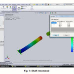
Fig. 1 shows the shafts resonance the which produces a displacement increases from fixed point to the midpoint of the shaft which will causes a failure to the shaft. The miss-alignment of the shafts causes an effect on the natural frequency of the shafts which are in misalignment conditions.
Figure 1: Shaft resonance
Conclusion