Discussion and Analysis of Ball Rolling (Ballizing) Process with Elastic and Plastic Deformation between Ball and Material
Pawan K. Upadhyay1, Pankaj Agarwal2 and A. R. Ansari1
¹Department of Mechanical Engineering, NIIT, Bhopal, India.
2Department of Mechanical Engineering, SSCT Bhopal, India.
DOI : http://dx.doi.org/10.13005/msri/090121
Article Publishing History
Article Received on : 09 Jun 2012
Article Accepted on : 03 Jul 2012
Article Published :
Plagiarism Check: No
Article Metrics
ABSTRACT:
In this regard ballizing may be the only means of producing exact size holes which can have no corner break and must also be burr free. Mated holes having slight elbow or s-bends can be finished in one pass and interrupted areas such as cross holes recesses do not create problems. Nor does ballizing throw burrs or chips into them as could occur if the piece were broached reamed or honed. The method applies to metallic materials, and they should have homogenous structure. If there are hard spots in castings, ballizing will not be carried out uniformly, any of the ferrous, non ferrous or stainless screw stocks can be processed with good results. Parts can also be ballized after case hardening or plating up to but not including the hard chromium level. The work piece should not be harder than 45 RC. Ball should have more hardness than work piece.
KEYWORDS:
Ballizing; Alluminum alloy; Alloy steel; C.L.A.; Elastic Pressure; Plastic deformation; BHN; Machining; Surface finish and deformation
Copy the following to cite this article:
Upadhyay P. K, Agarwal P, Ansari A. R. Discussion and Analysis of Ball Rolling (Ballizing) Process with Elastic and Plastic Deformation between Ball and Material. Mat.Sci.Res.India;9(1)
|
Copy the following to cite this URL:
Upadhyay P. K, Agarwal P, Ansari A. R. Discussion and Analysis of Ball Rolling (Ballizing) Process with Elastic and Plastic Deformation between Ball and Material. Mat.Sci.Res.India;9(1). Available from: http://www.materialsciencejournal.org/?p=1218
|
Introduction
The proposed research will have a direct impact on production process, such as precision tube sizing. Sizing of bushes etc, and final results will be of utility to industries. This will help in achieving high precision by selecting appropriate “Ball-Tube” combination.
Other carbon steels and alloy steels with harder balls. Ballizing could be done on soft metals like zinc. copper, lead, light metal, bearing metal and many other soft alloys.Application of lubricant and types of lubrication can be used.Higher loads can be choose for achieving more hardness. Work hardening in the internal diameter layer takes place upto 0.06 mm. Efforts can be made to increase this depth. The hole wall expands due to the interference between the ball and hole. The material of the ball is so selected that it is not permanently deformed. After the ball has passed through the hole, it adopts its original diameter, whereas the hole wall springs back by the amount of elastic expansion. some metal is also displaced by the plastic flow.
Analysis And Evaluation Of Plastic Deformation In Ballizing
Ballizing can be carried out with or without lubrication. Generally lubricated ballizing gives better results When ballizing is done on soft and ductile materials like Aluminum, the particles of base material get detached and remain stick to the ball.
If velocity is high and interference is more. Local welding is caused due to heating. With lubrication, ballizing can be carried out without any scoring of the particies from base metal.
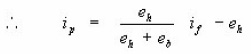
The value of b calculated from the circular contact can be applied for load calculation due to elastic mode in ballizing.

The axial force F elastic is given by equation (2) where 2b is width of contact p D is length of contact, p the radial elastic pressure (to be derived from Lame’s equation) and µ is coefficient of friction sticking conditions can be assumed to prevail between the ball and the hole wall and a value of µ equal to K/5.14 K = nearly equal o 0.2 is adopted.
The various values of different parameters are shown in the figures
This the contact between the ball and hole is circular with develop a mathematical mode to estimate Fp1 as a function of ball travel and accounting for the size of built up nose, however, a simplified model for the estimation of Fp1 is proposed.

Considering the effect of elastic material underneath the coronet
Figure 1:
Experimental Technique
A.Orthogonal Transformation :-
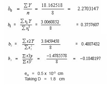
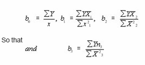
To facilitate the determination of b0, b1, b2 and b3 the values of x1, x2 and x3 should be so selected that
The values of coded variables x1 or x2 or x3 can be +1 ro -1 to satisfy the condition of orthogonally.
The relationship between the natural variables x’ and the coded variables x is based upon conventional transformation.
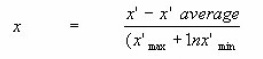
Since we will need coding in logarithmic form
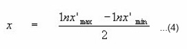
It can be verified that R.H.S. of eqn. (9) is equal to +1 when x’max is substituted for x’ in above equation and equal to -1 when x’min is substituted for x’ in above equation.
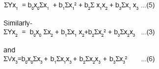
Mathematical Model for Ballizing
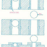
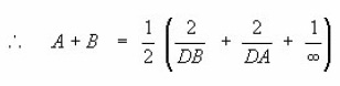
In Ballizing and elastic ball diameter ( Db) is passed through a cylindrical bush of inside diameter (dh). Where Db is only a few microns greater (Dh). to determine the width of contact the general case of Hertzian equations can be applied. and on the angle ψ between the principal planes of curvatures. m and n are constants whose value depends upon the value of A and
Since practically
Db H≈ Dh H≈ D say A + B=1/D
similarly B=A = 1/2 [2/Db-2/Dh + 0] = 1/D
Since Cos 2 ψ = -1 in Ballizing
For a Ratio

m=1 and n=1
Analysis Of Diagram For Numerical Value Obtained
for Ballizing process
Aluminium Alloy Bushes(Material)
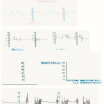
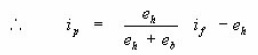
It is observed that with 170 and 70 microns interference respectively the final diameters obtained are 17.08 mm and 17.16 mm respectively.In the two bushes of 180 microns interference, from very rough surface as shown in fig. the final surface finish obtained was of 0.3 CLA, which indicates that a very good surface finish is obtained (fig.)
Figure 2:
In the two bushes, in which interference was kept only 70 microns, the surface finish was not so good as it gave the C.L.A. value as 0.75 (Reg. fig.)
Figure 3:
Figure 4:
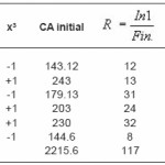
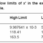
Observations Taking from figures for Calculation of Ratio
Observation Table
Observation Table
Calculations with help by diagrams
Where ,
x’1 , x’2, x’3 = Real independent variables
x1, x2, x3 = Coded variables
R = Dependent variables
k, a1, a2, a3 = Constants
b0, b1, b2, b3 = Constants
Cp-relation Factor
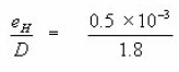
eH = 0.5 x 10⁻³ cm
Taking D = 1.8 cm
making it non dimensional
For Equation
We have
Results and Discussion
For Mild Steel Bush with 70 Microns Interference
E = 1.96 x 10⁶ kg/sq mc p = 9903 kg/sq cm
2 a = π R1 = 5.677 cm. µ = 0.3 R1 = 0.9 cm
R2 = 1.8 cm and b = 0.0042 cm
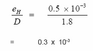
The value of eH calculated from the equation 3 which is
eH = 0.5 x 10⁻³ cm
Taking D = 1.8 cm
making it non dimensional
8.2 For Aluminum Bush of 170 microns interference
E = 0.675 x 10⁶ kg/cm2
μ = 0.34
R1 = 0.9 cm R2 = 1.8 cm
2a = 2 p R1 = 5.677 cm.
b = 0.0114 c,
p = 3342.70 kg/ sqcm
The value of eH calculated from the equation
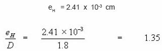
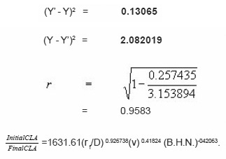
The intercept on the Y axis is 1.35 microns according to authors model and aimed at adopting equal to 1.
A value of 70 microns has been adopted for strain calculations in the case of steel, whereas an interference of 170 microns is adopted for Aluminum because of sinking in tendency of Aluminum, under the load of an indenting ball.
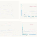
Fig indicate comparison between authors model and Experimental results.
Discussions
On the result of investigation following Concluding remarks can be made :
Effect of Interference is more pronounced than that of velocity. With more difference of hardness in ball and bush, improved surface finish can be obtained.
When soft and ductile metals like Aluminium are ballized the metal particles get separated from surface of bushes, without
lubricant.
These particles get stick to the balls during every pass, which need to be removed every time.
Both the results show values are quite high and curve fitting is satisfactory in both the cases.
Variation of load on the length of bush shown that, nearly at the center of the bush length the load is maximum.
Vibration in he load curve may be due to variation in the geometry accuracy while boring.
Some remark and Objectives of the Proposed work of Ballizing Process
This is having wide range of application and it is being used as a noble process (ballizing), with some Observations and Concluding remarks which are listed below :
Parts that have case hardened layer upto 0.4 mm, can be ballized, but beyond 0.4 mm case hardened depth, ballizing connot be carried out successfully.
When heat treatment is done after ballizing, sizing and finishing of the ballized hole get disrupted.
It has established that in a particular soft material (Medium Carbon Steel) when ballizng is done with a hard material ball
The required bore diameters can be obtained as mentioned in the diagram (Fig.)
Good results can be obtained by ballizing for the following material Sintered iron, sintered brass i.e. powdered metals.
Case hardened surfaces can also be ballized, but these should be free from hard chromium layer.
References
- Agrwal, A.S. : ‘Ballzing process for burnishing holes’ Dissertation for P.G. Diploma in Production Engineering (Royal College of Science and Technology Glasgow, U.K.). (1992).
- Fedrov, V.B. : Residual stresses and fatigue strength with centrifugal ball strain hardening. Trans. Of Ural polytechnical Institute, Col. 112 (1991).
- Investigation of some effects of Ballizing on Aluminium and Mild Steel. First Indian Engg. 9-13 Calcutta (1987).
- Investigation of Elastic and plastic forces in Ballizing process [Ball Burnishing] for Aluminium and Mild steel. First Indian Engg. 9-13 Calcutta (1987).
- Investigation of surface Effects in Ballizing on Aluminum and Mild Steel. First Indian Engg (1988).
- Shneider et. al., Yu.G. : ‘Vibratory burnishing of machine tool parts ‘Machine and tooling 3: 50 (2002).
- Ryzhov, E.V. ‘Increasing contact stiffness by vibratory burnishing’ machine and tooling 1: 59 (2002).
- Vestnik Mashinostroeniya : ‘Self Centering Three Roller Attachment with Instrument to check Burnishing Forces’. Russian Engineering Journal, Vol.57, Issur-7, pp59-69 [2007]
- Enlimash and orgstankinprom : Improving gear efficiency by Burning Machine and Tooling, 3: 54 (1999).
- Torbilo, V.M. and Chekin, G.I. : Accuracy of diamond burnishing Machine and tooling No. 5: 32 (1999).
- Kononenko, V.T. and shamlin, V.Yu. : ‘Carbide burnishing unit for broaches’, Machine and Tooling 8: 35 (2005).
- Khovrostukhin, L.A. and Mashov, V.N. : Effect of diamond burnishing on chromium plating Machine and Tooling 6: 45 (2000).

This work is licensed under a Creative Commons Attribution 4.0 International License.