Mechanism of Ball Burnishing Process for Radius of Curvature for Elastic and Plastic Deformation between Ball and Hole
Pankaj K. Upadhyay1, Pankaj Agarwal2, A. R. Ansari3 and Ravindra Mohan
¹Department of Mechanism Engineering, NIIST, Bhopal, India.
2Department of Mechanism Engineering, SCT Bhopal, India.
3Department of Mechanism Engineering, NIIST, Bhopal, India.
Article Publishing History
Article Received on : 30 Mar 2012
Article Accepted on : 05 May 2012
Article Published :
Plagiarism Check: No
Article Metrics
ABSTRACT:
Ball burnishing (ballizing) chip less process which produces a smooth surface and surface hardness. The pressure generated by the ball exceeds a plastic deformation stage and create a new surfaces. The plastic deformation created by ball burnishing is a cold flows under pressure into the valleys surface is smooth, Ballizing is a technique for sizing and finishing holes in metal components. It is a rapid and relatively low cost process. A suitably oversized precision ball is pressed through an unfinished undersized hole, A simple tooling such as a hardened ball and a push rod is required for this process. However an intensive analysis is essential for analysing the mechanics of the process. The ball burnishing is very useful process to improve upon surface roughness and can be employed. It will help to impart compressive stress and fatigue life can be improved. The Al alloy is a difficult to machine material and burnishing is difficult process for this grade material. A low surface roughness and hardness was obtained in increasing the operating parameters. It may develop flaw and micro cracks on the surface.
KEYWORDS:
Ballizing; Alluminum alloy; Alloy steel; C.L.A; Elastic pressure; Plastic deformation; BHN; Machining; Surface roughness; Technology devices and equipment
Copy the following to cite this article:
Upadhyay P. K, Agarwal P, Ansari A. R, Mohan R. Synthesis, Mechanism of Ball Burnishing Process for Radius of Curvature for Elastic and Plastic Deformation between Ball and Hole. Mat.Sci.Res.India;9(1)
|
Copy the following to cite this URL:
Upadhyay P. K, Agarwal P, Ansari A. R, Mohan R. Synthesis, Mechanism of Ball Burnishing Process for Radius of Curvature for Elastic and Plastic Deformation between Ball and Hole. Mat.Sci.Res.India;9(1). Available from: http://www.materialsciencejournal.org/?p=1211
|
Introduction
Ball burnising used the surface integrity must be maintained Plastic deformation, micro- crack, phase transformation and residual stress. It is a cold working process and involves plastic deformation under cold working conditions by pushing hard. The burnishing process help to improve surface roughness super finishing.
Mathematical models incorporating the effect of speed, hardness of work piece on the surface finish improvement are essential for a thorough investigation of this process. This will lead to discovery of important parameters on surface to engineer to achieve desired goals of centre line average values etc.
In this technique metal is not removed, as such it differs form other hole finishing processes. The burnishing action of ballzing not only refines the surface structure but also gives a layer of denser material. The surface layer is deformed very little; but and finishing of the bore depends upon the accuracy and smoothness of the ball.
The hole wall expands due to the interference between the ball and hole.The material of the ball is so selected that it is not permanently deformed. After the ball has passed through the hole, it adopts its original diameter, whereas the hole wall springs back by the amount of elastic expansion. some metal is also displaced by the plastic flow.
Ballizing can be carried out with or without lubrication. Generally lubricated ballizing gives better results When ballizing is done on soft and ductile materials like Aluminum, the particles of base material get detached and remain stick to the ball. if velocity is high and interference is more. Local welding is caused due to heating. With lubrication, ballizing can be carried out without eny scoring of the particies from base metal.
Favorable Conditions For Ballizains Mechanics of Ballizing
The ballizing process can be explained with the help of two distinct models. The first one comprises of conditions of elastic contact between the ball and the hole. over a width 2b. The Hertizian equations of contact between two elastic bodies can be applied to estimate the normal pressure between the ball and the bush material.
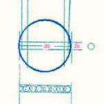
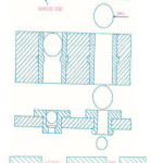
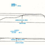
The material of the bush ahead and underneath of the ball is also subjected to plastic flow. The interference between the ball and the hole is substial say 90 microns and 180 microns for a hole diameter of 18mm and a coronet or builtup edge of the plastically deformed material is developed ahead of the ball as shown in fig. slip line field technique can be applied to estimate the pressure between the ball and the hole due to plastic deformation. The force required for Ballizing is the sum of elastic and plastic contact.
Figure 1:
Research Technique and Methodology Used
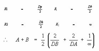
Mathematical Model with Hertzian Equation to Ballizing: In Ballizing and elastic ball diameter Db is passed through a cylindrical bush of inside diameter dh. Where Db is only a few microns greater Dh. to determine the width of contact the general case of Hertzian equations can be applied.
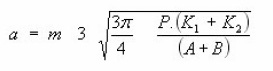
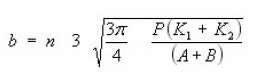
A and B are constants depending on the magnitude of principal curvatures of the surfaces in contact
and on the angle y between the principal planes of curvatures.
m and n are constants whose value depends upon the value of A and B
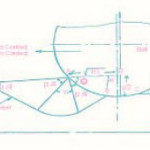
Radius of curvatures of contacting bodies in two mutually perpendicular planes in ballizing. In the ballizing problem
This proves that the contact between the ball and hole is circular with
Since practically Db ~ Dh ~ D say A + B = 1/D
similarly B=A = 1/2 [2/Db-2/Dh + 0] = 1/D
Since Cos 2 y = -1 in Ballizing
For a Ratio
m=1 and n=1
Figure 2:
Figure 3:
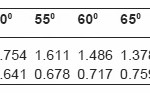
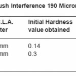
Table 1:
Analysis And Tabulation
The value of m and n for various values of q are given in the table below extension for 0 < q < 300
The value of b calculated from the circular contact can be applied for load calculation due to elastic mode in ballizing.

The axial force Felastic is given by equation (2) where 2b is width of contact p D is length of contact, p the radial elastic pressure (to be derived from Lame’s equation) and µ is coefficient of friction sticking conditions can be assumed to prevail between the ball and the hole wall and a value of µ equal to K/5.14 K = nearly equal to 0.2 is adopted
Figure 4:

The value of q can be approximately calculated as
Plastic Deformation In Ballizing
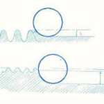
In ballizing the ball tends to iron out the surface of the hole wall. Depending upon the values of if and Hmax. two modes of plastic flow can be contemplated.
When if < Hmax’ the ball will ride over the asperities and cause surface finish improvement owing to filling of troughs by crests.
When if > Hmax’ the ball carries out a forward extension of the material in the hole wall. In the experimental work taken up for research the if = 40 μm and hmax has a maximum value of about 25 μm
There is a development of a built up nose (coronet) ahead of the ball as ballizing proceeds. The size of the built up ‘coronet’ increases in size from magnitude zero at the beginning of the stroke to its full size by end of the stroke.
Contact between ball and material of the holes comprises of elastic portion. Thus the Ballizing process is the outcome of Elastic and Plastic properties in combinations.
Plastic Portion
Due to extrusion of the material ahead of the ball with plastic contact length AB, a build up nose is developed. It is difficult to develop a mathematical mode to estimate Fp1 as a function of ball travel and accounting for the size of built up nose, however, a simplified model for the estimation of Fp1 is proposed.
Figure 5:
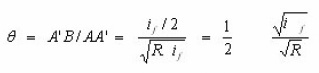
Thus the angle q will be 0.005 radians (for if = 0.18 mm and R = mm)
Neglecting q in equation (3) we get
Considering the effect of elastic material underneath the coronet
Results And Discussion
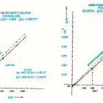
Linear Relationship
For M.S. ip/D = 0.989 (if/D) – 0.49275 x 10⁻³
For Aluminium : ip/D = 0.9644 (if/D) – 2.2 x 10⁻³
Corelation Factor : (r)
For CLA equation : 0.9583
For load equations : 0.8677 In the above equation ‘v’ is in mm/minute
Load Equation :
Load = 3653.4858 (rf/D)1.4646 ( v )0.08075 (B.H.N.)1.16394
Surface Effects
With the dame ball and bush diameters
Figure 6:
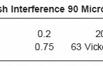
Table 2:
Table 3:
Figure 7:
Discussions
following Concluding remarks can be made
Ballizing process distorts and reduces the grains size which increases hardness in the ballized layer. The thin surface film gets hardened up to a depth of 0.06mm, in Mildsteel, and 0.08 mm in Aluminium.
Width of contact (2b) is also found to be more with more interference or in softer material.
Temperature does not rise so much during ballizing that it may affect the surface finish.
Linear relationship in ballizing show that there is no plastic deformation in M.S. upto if/D = 0.547 X 10⁻³ and in Aluminum upto if/D =0.372 X 10⁻³.
Linear relationship between ip and if is plotted in the authors model. Slightly different values are obtained which affect m and c as shown in figs. 5.4 & 5.5.
References
- Gazen, G.A. : ‘Ballizing A High production Tool’Tooling and production, October-[1998]
- Gazen, G.A. :‘Ballizing’ Automatic Machining, (1999).
- Dart, A. : ‘Improving Fatigue Strength of Metals-1, Machinery and production Engineering, 4 August (2004).
- Agrwal, A.S. :‘Ballzing process for burnishing holes’ Dissertation for P.G. Diploma in Production Engineering (Royal College of Science and Technology Glasgow, U.K.). (1992).
- Fedrov, V.B. : Residual stresses and fatigue strength with centrifugal ball strain hardening. Trans. Of Ural polytechnical Institute, Col. 112 (1991).
- Enlimash and orgstankinprom : Improving gear efficiency by Burning Machine and Tooling, 3: 54 (1999).
- Torbilo, V.M. and Chekin, G.I. : Accuracy of diamond burnishing Machine and tooling No. 5: 32 (1999).
- Kononenko, V.T. and shamlin, V.Yu. : ‘Carbide burnishing unit for broaches’, Machine and Tooling 8: 35 (2005).
- Khovrostukhin, L.A. and Mashov, V.N. : Effect of diamond burnishing on chromium plating Machine and Tooling 6: 45 (2000).
- Emel Tanov, V.N. : Burnishing shaft fillets machine and tooling, 6: 31 (2001).
- Shneider et. al., Yu.G. : ‘Vibratory burnishing of machine tool parts ‘Machine and tooling 3: 50 (2002).

This work is licensed under a Creative Commons Attribution 4.0 International License.