Shyam Kumar Saphi and H. N. Mishra
Department of Physics, C. M. Science College Darbhanga - 846 004, India
DOI : http://dx.doi.org/10.13005/msri/090209
Article Publishing History
Article Received on : 25 Oct 2012
Article Accepted on : 30 Nov 2012
Article Published :
Plagiarism Check: Yes
Article Metrics
ABSTRACT:
In this research paper a short review on smart antenna is presented. The smart antenna consisting of micro strip patches array has been presented. It will enable a higher capacity in wireless networks by effectively reducing multipath and co-channel interference. This is achieved by focusing the radiation only in the desired direction and adjusting itself to changing or signal environment. A Nobel technique is investigated to form the desired shape forming of beam. This has become a part of range improvement and increase in capacity of smart antenna.
KEYWORDS:
Smart antenna; Micro strip patch arrays; Range improvement
Copy the following to cite this article:
Saphi S. K, Mishra H. N. A Nobel Smart Antenna for Broad-Band Applications. Mat.Sci.Res.India;9(2)
|
Introduction
Smart antennas are antennas arrays that are combined with signals processing in space and real time. Such antennas have their special need in cellular and mobile communication systems. The smart antennas have the properties of increasing the spectrum efficiency, channel capacity and coverage range. They have ability to provide certain channel in certain direction. They are able to reduce the propagation problems such as multipath fading, co-channel interference and have capacity to improve communication indices1-3. The smart antennas are characterized as adaptive array antennas, intelligent antennas, spatial processing and digital beam forming antennas. Mainly there are two types of smart antennas, the switched beam smart antenna and adaptive arrays smart antennas. The switched beam smart antenna divides the communication area into micro sectors. Each micro sector contains a predetermined fixed beam pattern. The adaptive system dynamically alters the pattern to optimized communication performance4,5. The adaptive array theory is based on optimization method and on real time response in a transit environment. Smart antennas can be analyzed for different network topology and mobility scenario .Their geometry is analyzed with appropriate feed network and algorithms for fast beam forming and direction of arrival. The cost of smart antennas continues to be the most critical issues.
The early smart antenna systems were designed for use in military applications to suppress interfering or jamming signals from the enemy6. Since interference suppression was a feature in this system, this technology was borrowed to apply to personal wireless communications where interference was limiting the numbers of users that a network could handle. It is major challenge to apply smart antenna technology to personal wireless communications since traffic is denser. Also, the time available for complex computations is limited. However, the advent of powerful, lowcost, digital processing components and the development of software-based techniques has made smart antenna systems practical reality for cellular communications systems.
Basic working mechanism
A smart antenna system can perform the following functions: first the direction of arrival of all the incoming signals including the interfering signals and the multipath signals are estimated using the direction of Arrival algorithms. Secondly, the desired user signal is identified and separated from the rest of unwanted incoming signals. Lastly a beam is steered in the direction of desired signal and the user is tracked as he moves while placing nulls at interfering signal directions by constantly updating complex weights.
It is quite evident that the direction of radiation of the main beam in the array depends upon the phase difference between the elements of the array. Therefore, it is possible to continuously steer the main beam in any direction by adjusting the progressive phase difference â between the elements. The same concept forms the basis in adaptive array sys in which the phase is adjusted to achieve maximum radiation in the desired direction.
In a beam forming network typically the signals incident at the individual elements are combined intelligently to form a single desired beam formed output. Before the incoming signals are weighted they are brought down the baseband or intermediate frequencies (IF’s). The receivers provided at the output of each element perform the necessary frequency down conversion. Adaptive antenna array systems use digital signal processors (DSP’s) to weight the incoming signal. Therefore, it is required that the down-converted signal can be converted into digital format before they are processed by DSP. Analog to digital converters (ADC’s) are provided for this purpose. For accurate performance, they are required to provide accurate translation of the RF signal from the analog to digital domain. The digital signal processors form the heart of the system, which accepts the IF signal in digital format and the processing of digital data is driven by software. The processor interprets the incoming data information, determines the complex weights (amplification and phase information) and multiplies the weights to each element output to optimize the array pattern. The optimization is based on a particular criterion, which minimizes the contribution from noise and interference while producing maximum beam gain at the desired direction. There are several algorithm based on different criteria for updating and computing the optimum weights.Many methods have been proposed to achieve phase
shifting without an electronic phase Shifter, namely: Electromechanical tuning method using a piezoelectric transducer (PET)6; Beam steering by means of a coupled-oscillator technique2, Optical beam forming networks Based on liquid crystal phase shifters; Optical techniques for beam steering by ferrite-based Patch arrays7-9 For the application of semi-smart antennas to achieve beam steering in real-time, a novel phase-Shifting method is presented. By non-mechanically adjusting the value of the effective dielectric Constant of the length of the dielectric plates, it is possible to perform beam streering without Employing methods of digital phase shifting. This permits simpler construction and lower costs. The structures were simulated using the commercial software, Ansoft HFSS Element methods(FEM)
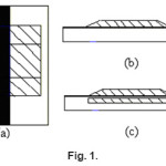
Figure 1
Simulations of Transmission Line Phase Shifting
with Dielectric Plates
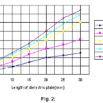
The first is with a single –layer dielectric plate attached to the transmission line, as shown In Fig.1(b); the second is with a dual-layer combination of dielectric plate, both attached to, And 0.1mm under, the transmission line, as shown in Fig1(c).The edge of the upper dielectric Plate are tapered to suppress the reflection loss. The substrate has a permittivity of 4.0 F/m and dimensions of (40*12*2)mm3. The width of the transmission line is 2mm. The dimensions of the dielectric plate Is (L*10*1) mm3,where 0< L<30mm. Fig2shows the phase of S21simulated with singlelayer dielectric plate.Fig.5 shows the phase of S-21simulated with a dual-layer of dielectric plates. Clearly, phase shift can be seen introduced by using a Single – layer dielectric plate or a dual-layer of dielectric plates. It is noticeable that phase increases With the increase the effective permittivity as well as with the increase in length of the dielectric plate. The dual-layer structure produces a more evident phase shift, of which the phase Shift has increased nearly 66.7% (when L=5mm, 107.7% (when L=20mm, and 115.9% (when L=30mm,) respectively, comparing to singlelayer structure. This is attributed to a Heavier attenuation of the propagation constant.
Figure 2
Array Correlation Matrix
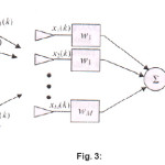
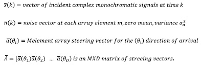
Many of the AOA algorithms rely onthe array correlation matrix. In order tounterstand The array correlation matrix. Let us begin with adescription of the array, the received signal, And the additive noise. Figure (4 ) depicts a array with incident plane waves from various direction.It also shows D signals arriving from D direction.
They are received by an array Of M elements with M potential weights Each received signal xM(k) includesadditive white Gaussian zero with mean noise. Time is represented by the kth time sample. Thus, the array output y can be given in the following form:
Figure 3
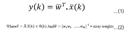
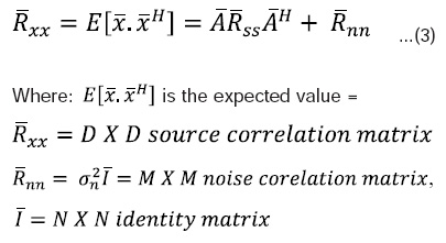
The array correlation matrix. Let us begin with a description of the array, the received signal, And the additive noise. Figure (4 ) depicts a array with incident plane waves from various direction.It also shows D signals arriving from D direction. They are received by an array Of M elements with M potential weights The D-complex signals arrive at angles θi and are intercepted by the M antenna elements. It is initially assumed that the arriving signals are monochromatic and the number of arriving signals D<M. it is understood that the arriving signals are time varying and thus our calculations are based upon time snapshots of the incoming signal. Obviously if the transmitters are moving, the matrix of steering vectors is changing with time and the corresponding arrival angles are changing, unless otherwise stated, the time dependence will be suppressed in Eqs. (1) & (2). In order to simplify the notation let us define the M X M array correlation matrix Rxxas.
H:superscript is the Hermit an operator (transpose complex conjugate
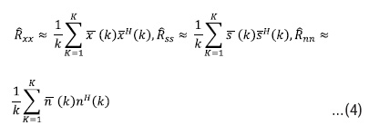
The exact statistics for the noise and signals are unknown, but we can assume that the process is ergodic. In that case the correlation can be approximated by the use of a time- averaged correlation. In that case the correlation matrices are defined by function that gives an indication of the angles of arrival based upon maxima vs. angle. This function is traditionally called pseudospectrum P(θ) and the units can be in energy or in watts .
The exponential growth of wireless communications system and the limited bandwidth available for those systems has created problems which all wireless providers are working to solve. One potential solution to the bandwidth limitation is the use of smart antenna systems. The demand for increased capacity in wireless networks motivated recent research to ward wireless systems that exploit space selectivity. As a result there are many efforts devoted to the design of smart antenna arrays. The term smart implies the use of signal processing in order to shape the beam pattern according to certain conditions. For an array to be Smart implies sophistication beyond merely steering the beam to a direction of interest. Smart essentially means computer control of the antenna performance. Smart antennas hold the promise for improved radar system, improved system capacities with mobile wireless, and improved access.
Conclusion
To acquire the desired radiation pattern from the base station following negotiation, a novel micro-stripphased-array antenna with single layer or dual layer dielectric plates may be employed,. The dielectric plates are designed to work as phaseshifters between the elements of the array. By nonmechanically adjusting the value of the effective dielectric constant or the length of the dielectric plates, it is possible to perform the beam steering without employing methods of digital phase shifting. This affords simpler construction and lower costs.
References
- Seong- Sikjeon, Yuanxum Wang, YongxiQian, and Tatsuo Itoh, “ A Novel Planar Array smart Antenna system with Hybrid Analog-Digital Beam forming”, IEEE Transactions on Wireless Communications, 2(1): (2002).
- Hubregt J. Visser, Array and Phased Array Antenna Basics, Jhon Wiley & Sons, Ltd., (2005).
CrossRef
- Dr. Mr. Mohammad Azad andHasnatShohel Ahmed “Development of smart for future generation wireless internet connection” IJCSNS international journal of computer science and network security, 10(10): (2010).
- Haneef “Paper presentation on Smart Antenna” Electronics , paper presentations, (2010).
- Toing SiehKiong, MahamadImail and Azmi Hassan “WCDMA forward Link Capacity Improvement by Using Adaptive Antenna with Genetic Algorithm Assisted MDPC Beam forming Technique Journal of Applied Sciences 6(8): 1766-1773 (2006).
- Minsoo Kim SungsooAhn, Seungwon Choi and Tapan K. Sarkar, “An Adaptive Beamforming Algorithm for Smart Antenna System in practical CDMA Environment” IEICE Trans. Common. Vol.E86-B, No. 3 (2003).
- Sang-Guy Kim, Kai Chang, “Independently

This work is licensed under a Creative Commons Attribution 4.0 International License.