Ankesh Kumar Pataskar, V.N. Bartaria and Abhishek Jain
University Institute of Technology, Barkatullah University, Bhopal, India.Lakshmi Narayan College of Technology, University Institute of Technology, Barkatullah University, Bhopal, India.
DOI : http://dx.doi.org/10.13005/msri/090212
Article Publishing History
Article Received on : 25 Oct 2012
Article Accepted on : 30 Nov 2012
Article Published :
Plagiarism Check: Yes
Article Metrics
ABSTRACT:
Axial flow fans are employed in heat exchangers and other engineering systems where the flow path around the fan becomes like a duct. The flow takes place along the axis of rotation of the rotor. The flow is essentially symmetrical to the axis. The design calculations are performed with presumption of flow through cascade of blade and it is the main governing factor of the design too. In this paper procedural calculation for an axial flow fan with profiled blade are presented. Calculations are tabulated for different parameter of radius and angles. On profiling, the increase of outlet angle has been shown which gives ultimate angle opening. The small corrections are therefore obtained. Different parameters used in the design are tabulated to get the calculation more accurately.
KEYWORDS:
Axial Flow Fan; Airfoil Blade Design
Copy the following to cite this article:
Pataskar A. K, Bartaria V. N, Jain A. Axial Flow Fan Design Parameter Affecting the Performance. Mat.Sci.Res.India;9(2)
|
Introduction
Axial Fan designers are frequently faced with the problem of designing high-efficiency fans at a given flow rate and for a given pressure duty. Design techniques are typically based on engineering experience, and may involve much trial and error before an acceptable design is found. An axial flow fan stage consists of a rotor made up a number of blade fitted to the hub. When it is rotated by an electric motor or any other drive, a flow is established through the rotor. The action of the rotor cause in increase in the stagnation pressure of air or gas across it. A cylinderalcasing encloses the rotor. It receives the flow through well shaped converging passage (nozzle) and discharges it through a diverging passage or diffuser. The number of blade in rotor varies two to fifty. As in axial fan, the flow is generally in the axial direction, Guide blade to recover statics pressure from the swiral downstream of the rotor.
Fan engineers are frequently faced with the problem of designing high-efficiency fans at a given flow rate and for a given pressure duty. Design techniques are typically based on engineering experience, and may involve much trial and error before an acceptable design is found.
Fan Design
We take External Diameter d2= 0.795
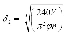
Then wefind Value ϕ =0.22
We find Value this Equation Ψ =0.130
Take Equation of Ψ
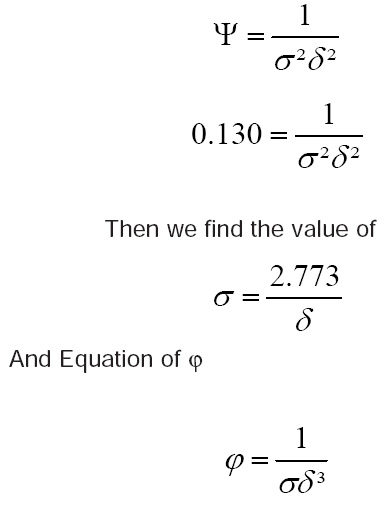
Equating both value Ψ and ϕ
Then Find Value σ=2.16 & δ=1.28
After the value speed coefficient σ and diameter coefficient δ is calculated, specific diameter r is read from the graph given in Figure by Eck Specific speed coefficient
We take a formula d2=795 mm ,& d1= 795 .28 = 225 mm, η=73%
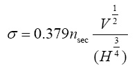
The meridional speed is obtained from
cm = V/(η/4)
cm = 15.122 m/sec
u2 = πd2n / 60
u2 = 60.73 m/sec
ϕ= cm / u2
ϕ = 0.24
Then,
Cu = ΔP/ηun
Figure 1
For t/ l, the best value of which range selects the first value are being at the tip of the blade. Thus we have take number of blade Z =9.
Z= (4π/ 1.5) [sin β2 /{1-(r1/r2)}]
Then find value β2 = 50.54° ≈ 50°
Then we take fig. blade pitch according to Zweifel by ECK
Take according to Zwifel β2= 30° Then we obtain value s/ l = 0.66 by fig. effect of Tip
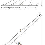
clearance of Weining Draw Velocity triangle
cm=ω2sin β2
ω2 = 19.74 m/sec
Then we obtain value of ω2 and
u= ω2 cos β2
Then we obtain value of u =12.68 m/s General relationship angle cot
β∞= ½ (cot
β1+ cot β2)
Then we find value of β∞=37.87°
cm=ω∞ sin β∞
ω∞=24.63 m/s
υ∞ / 2 = ( β2 – β1)/2=10°
βm=(β1+ β2)/2=40°
And value of t/l
Then we take value of by graph t= l cos βm then take l = 0.085 m And we take a value of μ = 0.61 And (1-μ)/μ =.0639
And Value ν = (ϑ∞/2) { (1-μ)/μ}
υ = 6.393
β1´= β1´- υ
β1´=23.607°
β2´= β2- υ
β2´=56.393°
Δβ= Δβ1(l/t)2 according to Weining graph determining the increase of angle by profiling s, profile thickness , l chord length Δβ=2.39°
We take value of
βm+ Δβ =42.39°
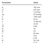
Table : Impeller geometry parameters
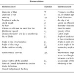
Table 2: Nomenclature
Conclusion
In the present paper design procedure for an axial flow fan applicable in heat exchangers and other engineering systems has been presented. The design calculations are performed with presumption of flow through cascade of blade and it is the main governing factor of the design too. The profiled blade theory is used for designing. Calculations are tabulated for different parameter of radius and angles. On profiling, the increase of outlet angle has been shown which gives ultimate angle opening. The small corrections are therefore obtained. In this paper important design parameters with particular values as obtained through calculation are listed. The data of important design parameters can be used for design optimization and energy conservation in application of axial flow fans.
References
- Ahmed F. Abdel Azim El–Sayed&Mostafa Mohamed M. Ibrahim,”Numerical Investigation of Different Tip Clearance Shape Effects on Performance of an Axial Flow Compressor Stage”,The Online Journal on Power and Energy Engineering (OJPEE).
- LI Yang & LIU Jie,”Internal flow mechanism and experiments research of low pressure axial fan with forward skewed blades”, Journal of hydrodynamics science directs.
- Hussain NOURI, Florent RAVELET, Farid BAKIR, and Christophe SARRAF, “Experimental investigation on ducted counter-rotating axial flow fans”, Author manuscript, published in “Proceedings of ASME-JSME-KSME Joint Fluids Engineering Conference 2011, Hamamatsu Shizuoka : Japan (2011).”
- C. Sarraf, H. Nouri, F. Ravelet,, F. Bakir, “Experimental study of blade thickness effects on the overall and local performances of a Controlled Vortex Designed axial-flow fan”, Author manuscript, published in “Proceedings of ASME-JSME-KSME Joint Fluids Engineering Conference hal- 00507786, version 2 – 25 (2010).
- Eck, B., “Fans”, Pergamon Press, 1973.
- Ali Aktürk&CengizCamci, “Axial Flow Fan Tip Leakage Flow Control Using Tip Platform Extensions”, Journal of Fluids Engineering Copyright © 2010 by ASME MAY 132 / 051109-1 (2010).
- Laszlo MOLNÁR1, Dr. JánosVad, “Design of a small –scale axial flow fan rotor of high specific performance”,
- D. N. So.rensen, M. C. Thompson & J. N. So.rensen, “Toward Improved Rotor-Only Axial Fans—Part II: Design Optimization for Maximum Efficiency”, Journal of Fluids Engineering , 122: 325 (2000).
- Eimad E. Elhadi& Wu Keqi, “Numerical simulation and modification 3d flow phenomena in an axial flow fan”, Task quarterly 7(2): 199–213 (2003).
- Young-Kyun Kim, Tae-Gu Lee, Jin-HuekHur, Sung-Jae Moon, and Jae-Heon Lee, “Flow Characteristics Impeller Change of an Axial Turbo Fan”, International Journal of Aerospace and Mechanical Engineering 4:1 (2010).
- S.J. van der Spryt T.W. von Backstrdml, “Performance of rotor-only axial fans designed for minimum exit kinetic energy”, R & D Journal, 18(3): (2002).

This work is licensed under a Creative Commons Attribution 4.0 International License.