Siddhanath V. Nishandar 1 , Ashok T. Pise1 and Shrikant S.Madiwale2*
1Department of Mechanical Engineering, Government College of Engineering Karad, Kolhapur, Maharashtra , India.
2Tolani Maritime Institute, Pune, Maharashtra, India.
Corresponding Author E-mail:Shrikantmadiwale@gmail.com
DOI : http://dx.doi.org//10.13005/msri.20.special-issue1.06
Article Publishing History
Article Received on : 01 May 2023
Article Accepted on : 11 Aug 2023
Article Published : 05 Dec 2023
Plagiarism Check: Yes
Reviewed by: Dr. Pei-Kang Sun
Second Review by: Dr. Felix Sahayaraj
Final Approval by: Dr. Jayanta Kumar Mahato
Article Metrics
ABSTRACT:
To increase the performance of the thermal and flow devices with respect to the heat and flow characteristics in a pipe, different techniques are widely used such as modification in the fluid flow and modifications in the pipe geometries. Several boosting modified tubes, including a finned tube, a tube with ribs, a tube with spirally roughened walls, a corrugated tube, a fluted tube, a helical tube, an elliptical axis tube, and others, act to increase the turbulence in fluid flow and are the examples of modifications in the geometries. As compared to the modification in the pipe geometries with modification in the fluid flow, the fluid flow modifications attract more cost and most are the techniques are not so economical. In the current paper, the comparative analysis is studied between the simple pipe and pipe with dimples for heat and flow characteristics enhancements with the help of computational techniques. For pipe with dimples, the results were more satisfying as compared with the simple pipe. The maximum velocity build-up in the dimple pipe was 0.753m/s whereas in the simple pipe it was 0.604m/s, , that means there is a 24.66% increase in velocity in dimple pipe as compared with simple pipe. Also, vorticity was found to be more in the dimple pipe and which was 126000/s as compared with simple pipe 389/s , which means more than 100% increase in the vorticity. Heat transfer enhancement in the dimple pipe was observed in terms of an increase in the temperature and found to be a maximum of 418 K as compared with simple pipe only 409 K,which means that there is a 17.60% increase in the temperature in the dimple pipe. The computational study concludes that there were enhancements in the heat and flow characteristics of fluid flow in the dimple pipe as compared with the simple pipe.
KEYWORDS:
Computational Fluid Dynamics; Heat Transfer; Pulsating Flow; Vorticity;
Copy the following to cite this article:
Nishandar S. V, Pise A. T, Madiwale S. S. Computational Analysis of Pulsating Pipe Flow for Heat and Flow Characteristics Enhancement. Mat. Sci. Res. India; Special Issue (2023).
|
Copy the following to cite this URL:
Nishandar S. V, Pise A. T, Madiwale S. S. Computational Analysis of Pulsating Pipe Flow for Heat and Flow Characteristics Enhancement. Mat. Sci. Res. India; Special Issue (2023). Available from: https://bit.ly/3RsjwWV
|
Introduction
Numerous academics have been interested in pulsating flow because of its impact on heat transfer[16]. The efficiency of pulsating flow in terms of heat transfer through various geometries has been studied extensively in numerical and experimental research. Due to the significant importance of internal forced convection phenomena in many engineering applications, the studies of pulsing heat transfer and flow in ducts, tubes, and channels gained popularity 1. Finding the insights of pulsatile flows from the early decades of the last century has been the focus of several scholars. In tubes with circular, square, and oval cross sections, pulsating flow fields have been shown to cause the “annular effect,” which occurs when specific conditions exist. The maximum velocity at the channel cross-section occurs towards the tubewall rather than at its centre under operating flow conditions. The performance of numerous thermal engineering applications is impacted by the pulsing flow characteristics 2. These include combustion systems, internal combustion engines, reciprocating compressors, and refrigeration systems. Consequently, there has been an increase in interest in how pulsing flow affects convective heat transfer. It is considered that pure oscillatory and steady poiseuille flows make up pulsating flow 3.
Most prior researchers limited their studies to a relatively short range of these factors and took into account only a few operating variables (such Reynolds number, amplitude, and pulsation frequency) in their research 18. As a result, some researchers found that the heat transmission from pulsating flow increased, while others found that it increased very little, not at all, or even decreased 4. Reynolds number was maintained constant by certain researchers, and it was shown that the rate of heat transfer changed with pulsation frequency. It was discovered that heat transport is slightly improved by higher frequencies while it is slightly worsened by low frequency values19. The efficient transport of heat from corrugated tubes is another application of pulsing flow 5.
Studies on corrugated channels are crucial for determining how well pulsating flow operates in heat exchangers.17 According to the studies mentioned above, a crucial factor affecting the rate of heat transfer is the geometry’s structure where pulsating flow goes through. Under pulsating flow conditions, complex geometries like grooved surfaces offer superior heat transfer characteristics 6. These contradictory findings demonstrated that there is still a lack of knowledge regarding the heat transfer phenomenon in pulsating flow. There is a paucity of information in the literature on the heat transfer properties of pulsating internal flows in tubes20. On the other hand, due to the complex character of turbulent unstable flows, it is very challenging to provide a theoretical solution to problems of hydrodynamic and heat transport in the turbulent pulsating flows 7. The most trustworthy method of comprehending the phenomenon of unstable flows is therefore computational analysis of pulsing flows 8.
In the current study, the comparative analysis is studied between the simple pipe and pipe with dimples for heat and flow characteristics enhancements for pulsating flow with the help of computational techniques. For both the pipes the velocity, vorticity, temperature and pressure drop were found and analysed for flow and heat transfer enhancement for pulsating flow.
Computational Model and Mesh
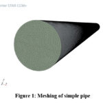
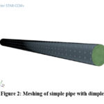
The computational domain was created for the simple pipe and for the pipe with dimple. The dimensions of the pipes were freeze according to the piping standards such as diameter of the pipe was 25.4 mm and length as 1000mm. Approximately the 14 dimples were arranged at the equidistant from each other on the outer periphery of the pipe for the 800mm length . First 200mm length kept without dimple in order to assure the formation of fully developed flow in the pipe. The type of the mesh created for the both the pipe were structured mesh by using Star CCM+ software. For good accuracy and conformity a mesh independence test was carried on the both the pipes. For simple pipe mesh count was 2.5 million, 2.8 million and 3.1 million and 2.8 million found to be with best agreement. For dimple pipe the mesh count was 3.2 million, 3.5 million and 3.8 million and 3.5 million found to be be with agreement for mesh independence test. Figure 1 shows the mesh of simple pipe and figure 2 shows the mesh of pipe with external dimple. Table 1 shows the geometry and mesh specifications.
Table 1: Geometry Specifications
|
Parameters
|
Simple Pipe
|
Simple pipe with dimple
|
|
Diameter
|
25.4 mm
|
25.4 mm
|
|
Length
|
1000 mm
|
1000 mm
|
|
Mesh count
|
2.8 million
|
3.5 million
|
|
Number of dimple
|
Nil
|
14
|
|
Type of Mesh
|
Structured mesh
|
Structured mesh
|
Model settings
Star CCM+ software was used for the model analysis. As there was a need to generate the pulsating flow so model applied to both the pipe was for transient conditions. K-epsilon turbulence model with transient conditions were applied with two layer all y+ treatment which ensures the minimum height of the first cell near the pipe wall13. Minimum y+ value basically used in order to capture the formation of boundary layer 9. Throughout the analysis density of the fluid was considered as constant i.e. incompressible flow.
Material properties
Air was considered as a working fluid with constant density in the both the pipe. Table 2 shows the properties of the air.
Table 2: Properties of the air
|
|
Properties
|
Value
|
|
1
|
Density
|
1.1845 kg/m3
|
|
2
|
Viscosity
|
1.85508*10-3 Pa-s
|
|
3
|
Specific Heat
|
1003.62 J/kg-k
|
|
4
|
Thermal Conductivity
|
0.026 w/m-k
|
|
5
|
Prandtl Number
|
0.9
|
Boundary Conditions
In the simulation setup, both the simple pipe and the pipe with dimples were defined with four boundary conditions, including inlet, outlet, wall, and default interior. At the inlet, a mass flow rate boundary condition of 0.001 kg/s was imposed. This choice of a relatively low mass flow rate was intentional to ensure enhanced heat transfer and improved flow parameters 11, 14. Studies have shown that lower mass flow rates can lead to higher heat transfer rates and improved fluid dynamics within the pipe. At the outlet, a pressure outlet boundary condition was applied to allow the fluid to exit the domain without reflecting back into the computational domain. The wall boundary condition, on the other hand, considered a constant heat source of 50 Watts. This heat source represented the constant heat input at the pipe wall, contributing to the heat transfer phenomenon within the pipe. The default interior boundary condition referred to the interior of the pipe itself. This allowed for the simulation to accurately represent the fluid flow and heat transfer processes occurring within the pipe.
Given that the model was set for transient conditions using the K-epsilon turbulence model, the convergence criteria were set to a residual value of 10^-3 for various variables, including mass, momentum, energy, kinetic energy, and its dissipation rate 12, 15. The convergence criterion ensured that the simulation results reached a stable and accurate solution, meeting the required level of precision for the analysis.
By adopting these well-defined boundary conditions and convergence criteria, the computational analysis provided valuable insights into the heat transfer and flow characteristics of both the simple and dimpled pipes. These findings contribute to the understanding of the performance enhancement achieved through the implementation of dimples in pipe designs for various heat transfer and fluid flow applications. Further research can leverage this knowledge to optimize the design and operation of such systems, with the potential for significant advancements in efficiency and performance.
Result and Discussions
Velocity Distribution
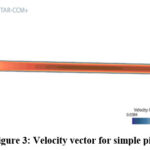
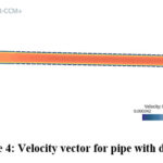
Figure 3 and Figure 4 present the velocity vectors for a simple pipe and a pipe with dimples, respectively. In the case of the dimpled pipe, the velocity vectors exhibit a noticeable increase in magnitude. This enhancement in velocity is primarily attributed to the presence of the boundary layer within the dimples, which facilitates the breakdown of the boundary layer and leads to the generation of turbulence in the flow. Consequently, the fluid flow experiences a substantial acceleration within the dimpled pipe compared to the simple pipe 10.
Quantitatively, the maximum increase in velocity observed in the dimpled pipe under transient conditions was measured to be 0.753 m/s, whereas in the simple pipe, it amounted to 0.604 m/s. This difference signifies a remarkable 24.66% increase in velocity within the dimpled pipe when compared to the simple pipe. The results demonstrate the pronounced impact of the dimples on enhancing fluid flow characteristics, validating their potential for enhancing heat and flow performance in such systems. Further exploration and analysis of these findings could pave the way for optimizing heat transfer and flow characteristics in a wide range of practical applications.
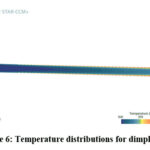
Temperature Distribution
Figure 5 and Figure 6 illustrate the temperature distribution for both the simple pipe and the pipe with dimples. In this experimental setup, the wall of the pipe served as a constant heat source, generating 50 Watts of heat. The presence of dimples on the exterior surface of the pipe facilitated heat transfer from the outside to the inside, leading to a notable effect on the temperature distribution.
As the heat flowed inside the pipe, the temperature of the fluid within the pipe began to rise. However, in the case of the dimpled pipe, the presence of turbulence in the flow, as opposed to a simple laminar flow, contributed to an overall increase in the temperature. This phenomenon is attributed to the increased mixing and enhanced heat exchange resulting from the turbulent flow induced by the dimples. The maximum temperature recorded within the dimpled pipe was 418K, while the simple pipe only reached 409K. This indicates a significant 17.60% increase in temperature within the dimpled pipe compared to the simple pipe. The results underscore the effectiveness of the dimples in promoting better heat transfer and temperature characteristics, making them a promising approach for heat and flow enhancement applications. To gain a deeper understanding of the underlying mechanisms and to optimize the design, further investigations into the heat transfer and flow characteristics of dimpled pipes are warranted. Additionally, exploring the impact of different dimple geometries and flow parameters can open up new avenues for achieving enhanced performance and efficiency in heat exchangers and various thermal systems.
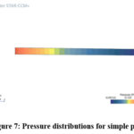
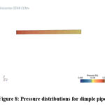
Pressure Distribution
Figure 7 and Figure 8 depict the pressure distribution for both the simple pipe and the pipe with dimples. Notably, the pressure drop in the dimpled pipe was recorded as 0.21 Pa, whereas in the simple pipe, it was higher, measured at 0.251 Pa. This difference in pressure drop can be attributed to several factors, with transient state conditions and higher turbulence within the dimpled pipe playing significant roles.
During the flow through the dimpled pipe, the transient state conditions cause fluctuations and variations in flow parameters, resulting in a more dynamic flow profile. These transient effects, coupled with the presence of the dimples, induce turbulence in the flow, enhancing mixing and promoting a more efficient exchange of momentum between the fluid and the pipe wall. In contrast, the simple pipe experiences a relatively smoother flow profile, with less turbulence and fewer dynamic flow fluctuations. As a consequence, the pressure drop in the simple pipe is relatively higher compared to the dimpled pipe.
The lower pressure drop observed in the dimpled pipe showcases its potential for reducing energy losses and improving overall system efficiency. Furthermore, these findings emphasize the practical significance of incorporating dimples in pipe design, particularly in applications that require efficient fluid transport, such as in heat exchangers and fluid conveying systems.
To gain a comprehensive understanding of the underlying flow mechanisms and the impact of various parameters on pressure distribution, further investigations through computational analysis and experimental studies are essential. Moreover, optimizing the dimple geometry and arrangement can lead to even more significant improvements in pressure characteristics, paving the way for more advanced and energy-efficient fluid transport systems in the future.
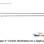
Vorticity
Figure 9 and Figure 10 provide insight into the vorticity distribution for both the simple pipe and the pipe with dimples. Remarkably, the vorticity recorded in the dimpled pipe reaches 126,000 per second, a significantly higher value compared to the simple pipe, where it is only 389 per second. This substantial difference in vorticity is primarily attributed to the presence of the dimples on the pipe’s surface, which play a critical role in generating turbulence and enhancing the fluid flow characteristics.
The dimples on the pipe surface induce a complex flow pattern, leading to a considerable increase in turbulence levels. The turbulence, in turn, contributes to the generation and sustenance of vortices within the fluid flow. These vortices play a crucial role in promoting efficient heat transfer in the dimpled pipe. The increased vorticity and turbulence in the dimpled pipe facilitate better mixing and convective heat transfer, allowing for more effective exchange of thermal energy between the fluid and the pipe’s wall. As a result, the dimpled pipe exhibits enhanced heat transfer capabilities compared to the simple pipe, making it a promising option for applications where improved heat exchange is desired.
The findings presented in this analysis highlight the significance of dimples in enhancing heat transfer through increased vorticity and turbulence. Further research into the underlying mechanisms and the impact of different dimple geometries on vorticity generation is essential to optimize the design and unlock even greater heat transfer enhancement potential. The integration of computational fluid dynamics (CFD) simulations and experimental investigations can provide valuable insights into the complex flow phenomena associated with dimpled pipes, thus paving the way for their efficient implementation in a wide range of heat transfer and fluid transport applications.
Conclusions
In conclusion, the presence of dimples on the exterior surface of the pipe plays a pivotal role in enhancing heat transfer and fluid flow characteristics. The dimples induce turbulence and swirl, leading to an increase in vorticity within the flow. This vorticity generation contributes significantly to improved heat transfer efficiency in the dimple pipe compared to the simple pipe. Additionally, the dimpled configuration results in a lower pressure drop, thanks to the break-up of the boundary layer, which reduces energy losses during fluid transport. Furthermore, the dimples promote a substantial increase in both velocity and temperature within the fluid flow. The higher velocity and temperature in the dimple pipe further validate the effectiveness of dimples in heat and flow characteristics enhancement. Overall, the dimples effectively generate more vorticity and vortex flow in the flow direction, fostering an environment conducive to enhanced heat transfer. These findings highlight the potential of utilizing dimpled pipes in various applications that require improved thermal performance and energy efficiency. Further research and optimization of dimple geometries can lead to even more significant advancements in heat transfer enhancement and fluid flow optimization.
Acknowledgement
We acknowledge the help extended by Mr. Somnath Nirali and Mr Narendra Bhole for providing the necessary help related to the software management and accesses.
Conflict of Interest
The author(s) declare(s) that there is no conflict of interests regarding the publication of this article
Funding Source
No funding was provided for the said study of the paper.
References
- V.S. Sonawane, M.R. Nandgoankar, C.M. Sewatkar, Frictional factor and flow characteristics in pulsating flow with high amplitude of pulsations, Materials Today: Proceedings,2022[https://doi.org/ 10.1016/j.matpr.2022.09.486]
CrossRef - Santhi Sree Nerella, Bhramara Panitapu, Sudheer V V S. Nakka, Fluid flow analysis in a closed loop pulsating heat pipe-simulation study,Materials Today: Proceedings,Volume 65, Part 8,2022,Pages 3558-3566 [https://doi.org/10.1016/j.matpr.2022.06.148]
CrossRef - P. Bharath Kumar, S. Srinivas,Pulsating flow of a non-Newtonian nanofluid in a porous channel with magnetic field,Materials Today: Proceedings,Volume 9, Part 2,2019,Pages 320-332 [https://doi.org/10.1016/j.matpr.2019.02.162]
CrossRef - A. Vijayalakshmi, S. Srinivas, BadetiSatyanarayana, A. SubramanyamReddy, Hydromagnetic pulsating flow of nanofluid between two parallel walls with porous medium, Materials Today: Proceedings,Volume 9, Part 2,2019,Pages 306-319 [https://doi.org/ 10.1016/j.matpr.2019.02.161]
CrossRef - J. Venkata suresh, P. Bhramara,CFD Analysis of Multi turn Pulsating Heat pipe,Materials Today: Proceedings, Volume 4, Issue 2, Part A,2017,Pages 2701-2710 [https://doi.org/10.1016/j.matpr.2017.02.146]
CrossRef - Piush Raj, Somnath Chattopadhyaya, Amitava Mondal, A review on continuous and pulsed water jet machining, Materials Today: Proceedings,Volume 27, Part 3,2020,Pages 2596-2604 [https://doi.org/10.1016/j.matpr.2019.11.071]
CrossRef - Shuichi Torii,Enhancement of heat transfer performance in pipe flow using graphene-oxide-nanofluid and its application,Materials Today: Proceedings,Volume 35, Part 3,2021,Pages 506-511 [https://doi.org/10.1016/j.matpr.2020.04.078]
CrossRef - H. Zontul, B. Şahin,Experimental investigation of convective heat transfer performance and hydrodynamics of pulsating flow through the rectangular grooved channel,Experimental Thermal and Fluid Science,Volume 141, 2023,110796 [https://doi.org/10.1016/ j.expthermflusci.2022.110796]
CrossRef - Ali Murat Binark, Mustafa Özdemir,An experimental study on heat transfer of pulsating air flow in metal foam subjected to constant heat flux,International Journal of Thermal Sciences,Volume 184,2023,107915 [https://doi.org/10.1016/j.ijthermalsci.2022.107915]
CrossRef - Yaxia Li, Qingping Yu, Sanchuan Yu, Bin Gong, Jing Zhang,Numerical investigation of pulsating flow structures and heat transfer enhancement performance in spherical corrugated helical tube, Applied Thermal Engineering,Volume 213,2022,118647[https://doi.org/10.1016/ j.applthermaleng.2022.118647]
CrossRef - Prayatna A Oddiwar, C.D. Koshti, CFD Analysis and Experimental Validation of Intake Swirl for Diesel Engine, International Engineering Research Journal Special Edition PGCON-MECH-2017, pp 1-7
- E. I. Kalinin, A. B. Mazo, A. V. Malyukov, V. M. Molochnikov & D. I. Okhotnikov, Pulsating flow past a spanwise rib in a channel at moderate Reynolds numbers, Fluid Dynamics volume 52, pages740–750 (2017)
CrossRef - Kubenko, V.D., Kruk, L.A. Pulsating liquid flow past a spherical body in an infinite cylinder. Int Appl Mech 35, 555–560 (1999). https://doi.org/
10.1007/BF02682177
CrossRef - Molochnikov, V.M., Mikheev, N.I., Mikheev, A.N. et al. Heat transfer from a cylinder in pulsating cross-flow. Thermophys. Aeromech. 24, 569–575 (2017). https://doi.org/10.1134/S0869864317040084
CrossRef - Bhalla, N., Dhiman, A.K. Pulsating flow and heat transfer analysis around a heated semi-circular cylinder at low and moderate Reynolds numbers. J Braz. Soc. Mech. Sci. Eng. 39, 3019–3037 (2017). https://doi.org/10.1007/s40430-017-0749-1
CrossRef - Chandrakant R. Sonawane, Hitesh N. Panchal, Siamak Hoseinzadeh, Mohammad Hadi Ghasemi, Ali Jawad Alrubaie, Ali Sohani. (2022) Bibliometric Analysis of Solar Desalination Systems Powered by Solar Energy and CFD Modelled. Energies 15:14, pages 5279.
CrossRef - Yupei Wang. Numerical simulation and experimental research on convective heat transfer on the shell side of a special-shaped tube heat exchanger [D]. Tianjin University, 2014
- Zhizheng Feng, Guobing Zhou, Laishun Yang, Jing He. Study on the enhanced heat transfer characteristics of cylindrical wing vortex generators in rectangular runners with equal heat flow [J]. Thermal Power in Engineering, 2013, 28(03) : 246 – 251 – 322
- Yaling He, Pan Chu, Tao Xie. Application and optimization of longitudinal vortex generator in tube-fin heat exchanger [J]. CIESC Journal, 2012, 63(03) : 746 – 760.
- A. K. Tiwari, P. Ghosh, J. Sarkar, H. Dahiya and J. Parekh, “Numerical investigation of heat transfer and fluid flow in plate heat exchanger using nanofluids”, Int. J. Therm. Sci., Vol. 85, pp.93-10
CrossRef

This work is licensed under a Creative Commons Attribution 4.0 International License.