Article Publishing History Article Received on : 9-Sep-2021 Article Accepted on : 5-Jan-2022 Article Published : 05 Jan 2022 Plagiarism Check: Yes Reviewed by: Dr. Umesh Jagannath Tupe Second Review by: Dr. Mohandas Final Approval by: Dr. Sudheesh K. Shukla
Article Metrics
ABSTRACT:
This work presents design and fabrication of efficient and economical ultrasonic utensil cleaning machine. Electrical energy is converted into Mechanical energy by transducer. Transducer vibrates with ultrasonic frequency supplied to it by the frequency producer. These vibrations produce cavitation bubbles in the solvent/water. The size of the bubbles is in micron range. The mass of the cavitation bubbles depend on the rate of recurrence of the transducer. These bubbles act as scrubber which scrub the surface of utensil thus removing the soils/dirt stick on it. The size of the bubble is so small it does not cause any damage to the surface of utensil. Higher the frequency, more homogeneous will be the cleaning. Rinsing is provided within the system which will make it more compact. To keep the contaminants away from the cleaned surface, sweep frequency is used. Rotation to the basket is given by the motor. This rotation helps to reduce the cycle time and also dry the surface of utensil by centrifugal action. So when the utensil is removed from the basket it is ready for use. By this technology cycle time will be reduced drastically. Without any human efforts it can clean the dirtiest stains from the oily utensils. All types of utensils can be cleaned whether it is ceramics, glass, copper, wood, aluminum, stainless steel, etc. This cleaning process is more hygienic and can clean more efficiently compared to conventional cleaning.
Desai S, Choudhari D. Design, Fabrication and Development of House hold Utensil Cleaning Machine. Mat. Sci. Res. India;18(3).
Copy the following to cite this URL:
Desai S, Choudhari D. Design, Fabrication and Development of House hold Utensil Cleaning Machine. Mat. Sci. Res. India;18(3). Available from: https://bit.ly/3zvjS4n
Introduction
Accurate and critical cleaning with the help of advance technique is now a day in industry as well as domestic are huge in demand to avoid situation like pandemic due to unwanted and unknown disorder. The rapid progression in various current advances and the reliable example in scaling down of parts have made a necessity for advanced tidiness levels. Contamination in the degree of monolayers can change surface properties like wettability, association, optical or electrical qualities. Particles in the degree follow poisons like non-unpredictable turns of events (NVR) in the degree of pictogram/cm2 and micrograms/cm2 ionic in equivalent reach or hints of usage have become part of the bit by bit stresses in local similarly as industry like food, clinical, texture, material, etc. With the help of advance manufacturing engineers’ components which have been used in significant enterprises like semiconductors, car, circle drive, optics, ophthalmic, glass, clinical, aviation, device coatings and drugs. For instance, while NVR has not been a vehicle industry issue as of in the relatively recent past, it has been earnest for the semiconductor and the plate drive organizations for a serious long time. Follow foreign substances are not satisfactory in businesses, as may cause bond disappointments in a multi-covering measure that follows clean-up. For clear reasons, totally clean area are an incredibly basic necessity in cleaning various products manufacturing as well as daily domestic and industrial use appliances.
In order to select a convincing cleaning strategy, the three key factors that are likely to influence the cleaning result are cleaning science, cleaning method and cycle limitation. To look subject at different mixes of accessible cleaning techniques and their viability, or need there-of is gigantic. Another and progressed cleaning technique with the utilization of ultrasonic offers a few benefits over other ordinary strategies. The investigation is in this exploration work predominantly on ultrasonic cavitation’s and the ultrasonic cleaning instrument. Ultrasonic innovation is demonstrated to be an adaptable strategy for cleaning different natural, inorganic and molecule impurities from different metallic and non-metallic area surfaces. Ultrasonic, the sound you can’t hear has arisen as a significant instrument in accomplishing the tidiness needed by today is steadily propelling innovation.
Ultrasonic cavitation and accuracy Cleaning
Accuracy or essential cleaning of sections is the completed departure of unwanted pollutions to an optimal pre-set level. The pre-set level is routinely the base level at which no adversarial impacts happen in a subsequent action. To accomplish this level, it is fundamental not to introduce new contaminant(s) into the cleaning system. For example, if the cleaning of regular and ionic unfamiliar substances is refined by a fluid cycle, have great water and the legitimate boundaries in the flushing stages. The new contaminants will be other, residual chemicals or presumably ionic substances from the wash water. Because the dryness is moderate, deionized wash water can react on certain metal surfaces at high temperatures and leave unwanted stains or marks.
Following are the means which is utilized in Ultrasonic Cavitation measure
Ultrasonic Cavitation and Surface Cleaning System:
Ultrasonic waves create and equally disseminate cavitation collapses in a fluid medium. The conveyed energies wander and enter significant into opening, surprise openings and regions that are far off. The clearing of poisons is reliable and uniform, paying little heed to the intricacy and the calculation of the substrates which is showed up in figure (a).
Cavitation age and Abundance
Figure (b) portray the age cavitation through at any rate three stages nucleation, development and rough breakdown.
Ultrasonic recurrence and molecule removal
Particle removal efficiency showed that the ability to eject micron and submicron particles in deionized water increased with increasing repeatability. At 65 kHz, the cleaning efficiency for one micron particle is 95% compared to 88% at 40 kHz. A similar expansion of the evaluation results was recorded for the 0.5 and 0.7 micron particles.
Aqueous and Semi Aqueous Ultrasonic cleaning
figure (c) shows the cavitation age in fluid and semi watery; it is a more mind boggling marvel. Cleaning science, as a component of the general cleaning process, is a vital component in accomplishing the ideal neatness.
Mechanisms of Cleaning
Two primary advances happen in surface area cleaning. The underlying advance is unfamiliar substance expulsion and the second is keeping those toxins from re-sticking to the surface. The removal of different pollutants includes various instruments appeared if figure (d, e f and g), in view of the nature and/or the class of the foreign substance. The component of expulsion of natural toxins by cleanser includes wetting of the pollutant just as the substrate. As indicated by Young’s condition, this will bring about expanding the contact point between the toxin and the surface.
Redisposition of Contaminants
Pollutants is repressed by another instrument, by framing a obstacle between cleaned area surface and eliminated toxin.
Cavitation and collapse
Cavitation “bubbles” are framed in spots of rarefaction when the fluid breaks or blasts because of the negative pressure component of the sound wave in the fluid. As the wave fronts pass, the cavitation “bubbles” oscillate under the influence of positive pressure, eventually developing to a precarious size. At long last, the vicious breakdown of the cavitation “bubbles” brings about collapses, which cause stun waves to be emanated from the sites of the breakdown. Decay and destruction of the ligament cavitations bubbles throughout the ultrasound-activated fluid, resulting from an effect commonly associated with ultrasound. Cavitation bubble collapses have been determined to generate excess temperatures of 10,000 ° F and pressures in excess of 10,000 PSI
An acoustic pulse outside the range audible to human hearing is the point at which ultrasound begins and the frequency range is equal to or greater than 20 kHz. Ultrasonic cleaning indicates that it uses sound waves in the 18/20 kHz or higher range.
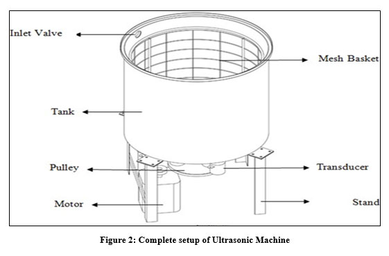
Constructions of Ultrasonic Cleaning machine
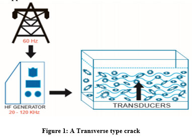
Ultrasonic waves are mechanical stress waves generated by ultrasonic transducers with high repeatability, high voltage current generated by electronic generators (energy generators). The average modern high power generator produces ultrasonic frequencies from 20 to 120 kHz.
Regular PZT transducers are ordinarily mounted on the base as well as the sides of the cleaning tanks or inundated in the fluid. The produced ultrasonic waves proliferate oppositely to the reverberating surface. The waves associate with fluid media to produce cavitation collapses. Focused energy ultrasonic waves make microvapour in the fluid medium, which develop to greatest sizes corresponding to the useful ultrasonic recurrence and afterward collapse, delivering the air energies. The higher the recurrence, the more modest the cavitation size. The extreme focus ultra sonics can likewise develop pits to a greatest throughout a solitary cycle. At 20 kHz the air pocket size is roughly 170 microns in measurement. At a higher recurrence of 68 kHz, the complete time from nucleation to collapse is assessed to be about 25 kHz. At various frequencies, the base measure of energy needed to create ultrasonic cavities should be over the cavitation.
Following
are the major terms related to the ultrasonic Cleaning:
Time
A typical time for testing is two to ten minutes, since not many parts are adequately perfect inside a couple of moments.
Temperature and Chemistry
Commonly, ultrasonic cleaning area in a fluid arrangement is ideal at 1400F. Some high pH devices will require an increase in temperature to improve the synergistic effects of science.
Proximity to the transducer part apparatus plan
Most ultrasonic cleaning frameworks are intended for explicit applications. A few sections need separate fixture to isolate the part for resulting measures. A few sections require moderate turning or vertical movement during the cleaning to guarantee basic tidiness.
Ultrasonic yield repeat
Vast majority of ultrasonic cleanings that are performed today in mechanical systems use 40 kHz as a base repeat. Lower frequencies like 20-25 kHz are used for huge masses of metal where ultrasonic damage is negligible.
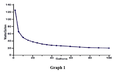
Stacking –the volume (plan) of the part being cleaned
Load of the part to be cleaned should be thought of, as to shape and thickness. A huge thick mass won’t permit inner surfaces to be completely cleaned (i.e., metal castings). A dependable guideline for stacking is that the heap by weight ought to be not exactly the heaviness of a large portion of the water volume. Sometimes, it is smarter to ultrasonically clean two more modest burdens, as opposed to one bigger burden.
Major application of Ultrasonic Cleaning Machine
Food Industry
Medical Instruments
Clothing and Textiles Industry
Specification of Ultrasonic Cleaning Machine
Following table show the components which are majorly required and its specifications
Table 1: Specification of ultrasonic Cleaning machine
SN
Name of the Components
Technical Specification
1
Frequency generator
Working Frequency
23.8 KHz(variable)
Working Current
0.65 A
Time control
0-600 minute
Ambient temperature
0-40 °C
Internal case overheat
protection
65 C°
Relative humidity
40%-90%
Outlook size
350mm x 200mm x 250mm(L x W x H)
2
Transducer
Model no.
S 25.38.1(Sparkler made)
Material
PZT4
Capacity
3700 pF
Frequency
25kHz
Radiating surface Diameter
50mm
Resonance Resistance
12Ω
Piezoceramics size
40 x 8(2 unit)
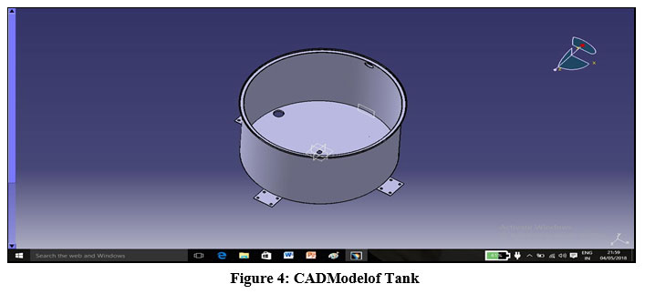
3
Tank
Material
UNS S30400
Diameter
380 mm
Length
365 mm
Thickness
1.2 mm
Volume
41 liters
material
Stainless Steel
Shape
Cylindrical shape
Type
Wire Mesh
5
Electric motor
type
Single Phase AC motor
6
Pulley Drive
Material
Aluminum
Input pulley diameter
62mm
Output pulley diameter
300mm
Input pulley Rpm
1350
Output pulley Rpm
300
Pulley groove angle
38º
7
Belt Drive
Type
V-belt
Material
Polyester Cord Neoprene Jacket
Strength
101.3kN/m2
Width(b)
05 mm
Height(h)
09 mm
Cross Section
Trapezoidal
Length
1000mm
Contact angle
152.2°
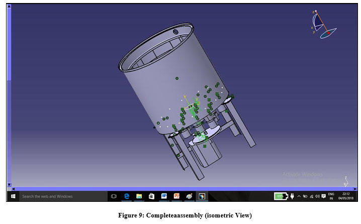
Mathematical calculation and Cad Model
Calculation of torque acting on Basket
For the
calculation of the torque required to rotate the basket, below calculation and
method is used.
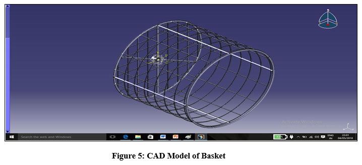
Following assumptions are made for the mesh basket:-
Cylindrical mesh basket is
assumed as rectangular plate rotating about the lateral axis at centre.
Pressure distribution is
linear.
Shape of utensil is assumed to be
rectangular shape.
Equal area method is used i.e. area of utensil and assumed rectangle is same.
There are three types of force acting on the basket
Pressure Force
Shear Force
Gravitational force
As the shape of utensil is generally
circular in shape but for the simplicity and sound designed, utensil shape is
assumed to be thin rectangle at the center of basket.
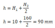
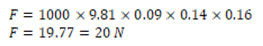
Let, Dimension of assumed rectangular plate = 280mm × 160mm
H1 = Height of utensil plate from top of basket= 10mm
H2 = Height of utensil plate from top of basket=160mm
=Average depth of plate from free surface i.e. top of basket
is calculated by the following formula:-
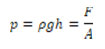
Pressure acting at various points under static condition is expressed as follow:-
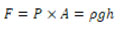
The above formula can be only used when the fluid is at rest i.e. stationary. As the maximum resistance or torque is required to just before the rotational motion, so till than the above equation can be applied. This leads to case of hydrostatic problem. Therefore the force acting on the plate is given by
The force acting oh half of the plate is
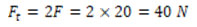
Therefore the total force acting on the plate is
As we all know that the torque is the product of force and the perpendicular distance for the axis of rotation i.e.
T = F x r
For the safety of the design it is assumed to be at a distance of 2/2 from the axis rotation
Therefore the force on one side of the plate i.e. 140mm of the length of plate
Therefore the total torque is the
Selection of Shaft from Catalogue
Material: – Stainless steel, grade 304
Grade 304/304L hardened
steel (1.4301/1.4307) is the most generally utilized business grade of tempered
steel and having magnificent erosion opposition at NRT. Therefore the shear
stress is given as follow
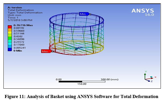
Following is the ANSYS of the basket; it has been performed by applying 10Nm moment to the shaft holder and keeping the top of basket fixed. Material used is structural steel. The results obtained are within the limit with maximum deformation of 0.767 mm at the joint of shaft holder.
Figure 11: Analysis of Basket using ANSYS Software for Total Deformation
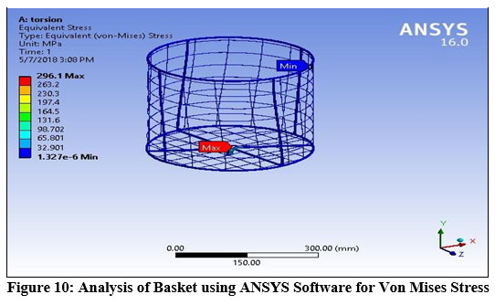
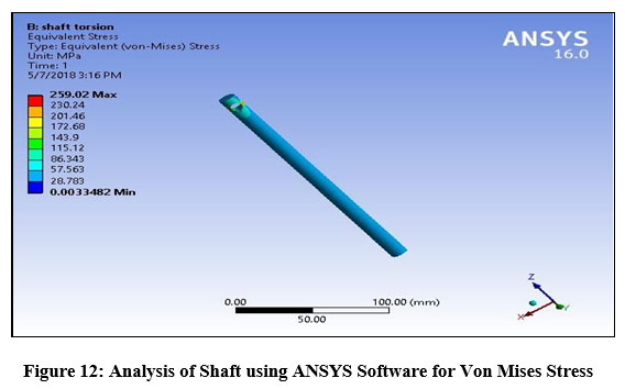
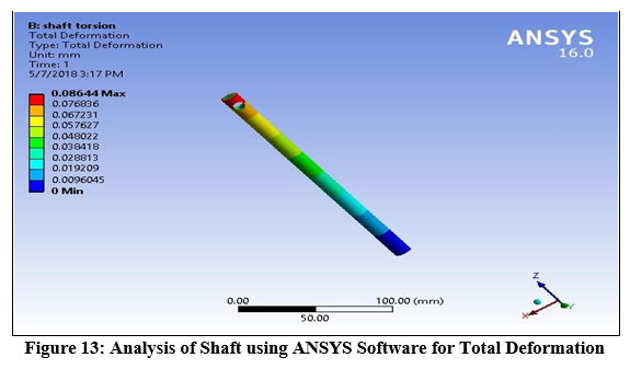
Following is the ANSYS of the shaft; it has been performed by applying 10Nm moment to the shaft having holed for fitting and fixing the down side. Material used is structural steel. The results obtained are within the limit with maximum stress of 259.01 MPa at the hole in the shaft.
Figure 13: Analysis of Shaft using ANSYS Software for Total Deformation
Design and fabrication of the machine is successfully completed. Following are the conclusion:-
Cycle time of the designed
machine in comparison with existing machine is very low.
No chemical
cleaner is required.
Energy
consumption is very less in comparison with existing machine.
Designed
machine is economic and environmental friendly.
Weight of the designed machine is less as compared to existing.
Acknowledgement
We would like to extend our sincere thanks to everyone who assisted in preparing , editing and proofreading of the manuscript.
Conflict of Interest
There is no conflict of interest.
Funding Sources
There are no funding source.
Reference
F. John Fuchs, “Continuing Developments in Ultrasonic Technology”, Controlled Environments™ Magazine – Contamination Controlled for the life sciences and microelectronics, September 2004.
Sami Awad, “Ultrasonic Cavitation and Precision Cleaning”, Crest UltrasonicsCorpration. Kshirsagar P.R., Solkar R.I., Hodekar A.M., Nikam M.P., Shinde B.G., “ Design, Fabrication and Experimental Investigations of Semi-Automatic Dishwashing Machine for Domestic Purpose”,IJARSE, Page No:- 980-981, 2017.
Jonny Johansson, “A Compact Ultrasonic Transducer using the Active Piezoceramic Material as Electronics Carrier”, Lulea Univ. of Tech, Page No:-S-97455. ASM Handbook Volume 5, “Surface chemistry-Ultrasonic Cleaning”, Page No. 44-47, 1994. CrossRef
Toshiaki Shimizu, “A study of the Standing Wave Indicator for the Ultrasonic Cleaner”, Tokyo Healthcare University Postgraduate School.Herlina Abdul Rahim, “Design and Manufacture an Ultrasonic Dispersion System with Automatic Frequency Adjusting Property”, UniversitiTeknologi Malaysia, March 2011.
J. Siddharth, “Experimental Investigation of Ultrasonic and Megasonic Frequency on Cleaning of Various Disk Drive Components”. PMR System, Ultrasonic Cleaning Theory and Application”.James R Hesson, “Fundamental of Ultrasonic Cleaning”, Hesson.

 and Dilip Choudhari