Performances of Silicon and Silicon Carbide Reinforced Nickel Electrodeposited Coatings Against Oxidation of XC100 Carbon Steels Exposed to Butane/Propane Combustion in the Open Air.
Désiré M.K. Abro1*, Collette A. Djassou1, Yao J. Adjoumani2and Benjamin K. Yao1
1Départment de Génie Chimique et Agro Alimentaire, Institut National Polytechnique Houphouët-Boigny, Yamoussoukro, Côte d’Ivoire.
2Département de Génie Electrique, Institut National Polytechnique Houphouët-Boigny, Yamoussoukro, Côte d’Ivoire.
Article Publishing History Article Received on : 03 Apr 2023 Article Accepted on : 10 May 2023 Article Published : 12 Jul 2023 Plagiarism Check: Yes Reviewed by: Dr. Prashant Koli Second Review by: Dr. Soumya Mukherjee Final Approval by: Dr. Carmiña Gartner Vargas
Article Metrics
ABSTRACT:
The protection of XC100 steel against oxidation due to butane/propane combustion by the mean of nickel (Ni), Nickel-Silicon (Ni-Si), and Nickel-Silicon carbide (Ni-SiC) electrodeposited coatings is reported. Gravimetric and microstructural characterizations of coatings after direct exposure to the gas flame were conducted. The results show that Ni-SiC coating improves the protection against oxidation of the underlying steel XC100 by decreasing the rate of weight gain by about 20 times against 13 times for Ni due to the decomposition of SiC particles in the boundaries of the coaxial grains network. Besides, the preferential oxidation of silicon particles to SiO2 into the nickel matrix revealed by EDS-X analysis confers stability to Ni-Si coating although its catching of mass is slightly higher than that of Ni-SiC. The charge transfer resistance Rct and the oxide electrical resistance Roxide extracted from Electrochemical Impedance spectroscopy agreed with gravimetric and microstructural observations.
KEYWORDS:
Nickel Composite coatings; Oxidation; Silicon Si, Silicon carbide SiC
Copy the following to cite this article:
Abro D. M. K, Djassou C. A, Adjoumani Y. J, Yao B. K. Performances of Silicon and Silicon Carbide Reinforced Nickel Electrodeposited Coatings Against Oxidation of XC100 Carbon Steels Exposed to Butane/Propane Combustion in the Open Air. Mat. Sci. Res. India;20(2).
Copy the following to cite this URL:
Abro D. M. K, Djassou C. A, Adjoumani Y. J, Yao B. K. Performances of Silicon and Silicon Carbide Reinforced Nickel Electrodeposited Coatings Against Oxidation of XC100 Carbon Steels Exposed to Butane/Propane Combustion in the Open Air. Mat. Sci. Res. India;20(2). Available from: https://bit.ly/43lvqoe
Introduction
Steel materials are widely used in industry. But the environmental conditions and/or the thermal solicitations in which they are used provoke the degradation of their properties and sometimes their destruction by oxidation. Oxidation is the degradation process of a metallic material that reacts with gaseous phases when exposed to temperatures above 500°C 1. Indeed, during the process, oxidative gases such as dioxygen O2 diffuse into the metal crystal lattice creating deformations, oxide layers, and cracks ending with the failure of the metallic material 2.
Then, combustion engines such as gas burners, gas turbines, and thermal power reactors as well as planes reactors are exposed affecting their performance, lifetime, and safety. To overcome oxidation, nickel-based alloys, and superalloys have been formulated and their performances studied 3-7.
At high temperatures, nickel forms a unique nickel oxide NiO. The growth of the NiO scale is parabolic and controlled by the double charge cations vacancies at temperatures above 800°C in pure oxygen at atmospheric pressure 8. For lower temperatures, grain boundaries formed in the scale act as short-circuits diffusion paths for nickel and oxygen ions reactions9, 10. Nickel oxide microstructure depends on the surface finishing and crystal orientation among others 11. As an example, mechanically polished samples show more open pores than those annealed at 700 °C during 20 H 11.
Concerning nickel-based superalloys, there are processed with ruthenium or hafnium by the cast, electron beam melting (EBM), arc melting or high-velocity oxy-fuel spray, dip coating or atomic layer chemical vapor deposition (ALCVD) 7,12-14. Zaretsky etal. attribute the good tensile strength of Inconel IN738LC and PWA 1483 alloys to a structural rearrangement at high temperatures 15. Nickel oxide (NiO) and spinel NiCrO4 are formed in the oxide scale 7,16. However, nickel superalloys are still subjected to fatigue, cracks, creeps, and spallation 5,7,17,18. Due to the cost and the machinery employed for bulk alloy materials elaboration, surface engineering such as electrodeposition has increasingly gained attention for some applications 19.
Electrodeposition is cheap to implement, and this technic provides complete control of the properties and the reproducibility of coatings 20. The method consists of the deposition of a metallic matrix by electrolysis onto a substrate. When growing with embedded particles, coatings are designed as Electrodeposited Composite Coatings (ECCs). Stott and Ashby reported that the nickel matrix electrodeposited is more efficient for anti-corrosion purposes than the cold-rolled nickel 21. Although nickel electrocoating with silicon and silicon carbide particles has been extensively studied, few papers have dealt with their high-temperature oxidation.
Generally, nickel-silicon ECCs, are deposited to promote silicon oxide SiO2 formation for developing thermal barriers against further diffusion of oxygen and so oxidation 22. In fact, in the study of Fellner and Cong, the mass change increases only by 0.22 mg/cm2 compared to bear steel which increases by 5.76 mg/cm2 at 700°C in the open air 23.
Concerning nickel/silicon carbide ECCs, data are limited to solid-state reactions at high temperatures between nickel and silicon carbide 24,25. In nitrogen and argon atmosphere, Burzynska et al. performed heat treatment of a 12% vol. Ni-SiC ECCs 26. They reported the formation of Ni3Si and Ni2Si at the nickel/silicon carbide interface as indicated by the Ni-Si system equilibrium phase diagram 27. Nevertheless, in this work, Ni5Si2 had not been found contrary to that reported by Schiepers et al.28. This might be due to the rapid phase transformation of Ni5Si2 to Ni2Si given the experimental time i.e. 30 min compared to 22 H of exposition in the work of the latter. In a vacuum, the interactions between nickel and silicon carbide result in the solid-state reactions leading to the formation of nickel silicides according to the sequence: Ni; Ni3Si + C; Ni5Si2 + C; Ni2Si + C that begins by thermal dissociation of SiC at Ni/SiC boundary 29. The thickness of nickel silicides grows according to a parabolic law and is controlled by diffusion. However, nickel carbide formation is not thermodynamically favored due to its positive value of Gibbs energy in the temperature range considered 25.
Thus, although nickel interaction with silicon and silicon carbide at high temperatures is already reported, very few papers dealt with the protection of carbonaceous steel against oxidation by the mean of Ni-Si and Ni-SiC ECCs at high temperatures. Herein, the thermal oxidation of Ni/Si and Ni/SiC ECCs deposited onto an XC100 steel substrate in an ambient atmosphere is investigated. A thorough physical characterization of the coatings after thermal treatment has been carried out by gravimetry, scanning electron microscopy (SEM) coupled with energy dispersive X-ray spectroscopy (EDS), and electrochemical impedance spectroscopy (EIS). Thus, a clear correlation between the structural and electrical properties of the different coatings and their anti-oxidation performances was determined.
Experimental
Materials and thermal treatment
The 20 mm x 20 mm x 0.7 mm substrate was cut off in a steel XC100 plate whose composition is shown in Table 1.
Table 1: XC100 Steel composition
Element
C
Si
Mn
P
S
Fe
Percentage (%)
0.95-1.05
0.15-0.3
0.25-0.55
Max 0.02
Max 0.02
Base
Nickel Ni, nickel-silicon Ni-Si, and Ni-Silicon carbide Ni-SiC coatings have been prior electrodeposited onto the substrate XC100 through a Watts-type bath 30,31. 1 wt% of silicon (Alfa Aesar; 1 – 5 µm) and silicon carbide (Goodfellow; 0.1 – 1 µm) were embedded respectively into Ni-Si and Ni-SiC Composite coatings.
To examine the efficiency of coatings against oxidation, thermal treatments were performed by exposition of samples to the blue flame of a propane-butane (20% – 80%) mixture gas in combustion once a day for 15 min for 23 days. The flame temperature is considered to be about 1327 °C 32. After thermal treatment, the samples were cooled to room temperature in the ambient. Thus, in this study oxygen is considered the only oxidative gas and its interaction with samples may result in a catch of mass. The rate of mass catching during thermal cycling was obtained according to Equation 1.
Where m0 (mg) is the weight of samples before thermal treatment and mi (mg) masses at cycle i.
Films characterization
Before and after each thermal treatment, the weight gain of each sample has been determined by a 10-2 mg accuracy electronic balance (Metler Toledo XS 205). The deposited surface morphologies and microstructures after thermal treatment were examined by scanning electron microscopy (SEM, Philips XL-30 FEG) coupled with an X-ray energy disperse system (EDS). Before microstructural characterization experiments of cross-sections, samples are cut and hot-mounted into resins before being mirror-polished according to metallographic operations. They are then etched in 50% nitric acid and 50% acetic acid solution or 1% HCl in ethanol.
Electrochemical Impedance Spectroscopy (EIS) experiments were employed to characterize the different protective coatings features by using a 100 mM KNO3 electrolyte through a three-electrode setup at open circuit potential and room temperature after thermal oxidation. Since EIS measurement cannot be performed at the operating temperatures range, the electrical properties of the scales formed after thermal treatment were tested specially to determine the charge-transfer resistance Rct and the scale resistance Roxide. These features were obtained by fitting the Nyquist diagrams recorded from EIS by the mean of Z-view software.
Results and Discussions
Mass evolution
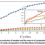
Figure 1 depicts the rate of mass change of samples under thermal cycling.
Figure 1: The mass evolution of samples and the zoom-in of composites coated samples during 23 cycles of exposition to the blue flame of butane/propane.
The profile of the rate of weight gain of XC100 presents three parts identified by three different slopes related to the formation of iron oxides. From the two first cycles, the rate of weight gain increases suddenly with a slope of 1.5. This rate then decreases from the third cycle and presents two slopes 0.3 and 0.12 as indicated by dashed lines in Figure 1. Within the period of investigation, the weight gain for coatings remains significantly lower compared to XC100 steel. The coated samples so present a better resistance against thermal cycling oxidation. For example, the catch of mass for nickel-coated sample Ni decreases by thirteen times and remains lower than that of XC100 at a rate of 0.6 (Figure 1) due to the oxygen affinity of iron. Gibbs energy of FeO and nickel oxide NiO, are respectively -361.6 KJ/mol and -250.8 KJ/mol at 1200 °C. The oxidation kinetic is so higher for iron.
Moreover, Ni-Si 30 composite-coated samples remain more stable than Ni-coated samples only up to the fourth cycle. From the fifth thermal cycle, the weight gain of Ni-Si films increases more than the Ni-coated sample. It seems that under the tested conditions, the presence of silicon particles in the Ni coating does not improve for a longer time hindering the oxygen diffusion inwards the material. On the contrary, Ni-SiC films show better stability because the rate of weight gain remains less than 0.5; twenty times lower than that of XC100. Then, the anti-oxidation properties depend on the type of coating.
Coating microstructures
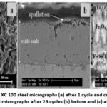
From the first day of thermal treatment, the surface of XC 100 develops wrinkles and numerous pores of about 250 nm in diameter as revealed in the micrograph in BSE mode, Figure 2a.
Figure 2: Top view of XC 100 steel micrographs (a) after 1 cycle and cross-section views of XC 100 steel micrographs after 23 cycles (b) before and (c) after etching.
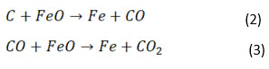
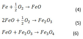
These pores may favour the decarburization of steel according to Equations 2 and 3 [33].
Moreover, spallation occurs due to mechanical stresses generated along with thermal cycling (Figure 2b). The etching of the oxide scale reveals a layer of hematite (Fe2O3) on the surface, intermediary blocky and coaxial grains of magnetite (Fe3O4), and an inner wüstite (FeO) layer (Figure). Then, the three slopes observed in the mass evolution rate indicate the formation of these three iron oxides according to the following global Equations 4,5, and 6 34,35.
Once formed from the first cycles, the vacancies in wüstite allow iron and oxygen ions to diffuse in opposite directions, and the oxide of degree III; hematite Fe2O3 forms but with a slower kinetic. The diffusion of Fe2+ outwards from the underlying metal and the inward diffusion of oxygen form Fe2O3 34. Then FeO combines with Fe2O3 to form magnetite Fe3O4.
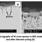
After 23 thermal cycles, the cross-section microstructure of Ni depicts a nickel oxide with voids and pores of about 2.5 µm depth, scattered and opened in the nickel coating (Figure 3a) 36.
Figure 3: Micrographs of Ni cross-section in BSE mode before (a) and after thermal cycling (b)
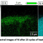
The etching of the cross-section presented in Figure 3b, confirms the compactness of the NiO layer that passivates the sample Ni against further oxidation. Energy dispersive analyses of pores are shown in Figure 4.
Figure 4: Energy dispersive spectral images of Ni after 23 cycles of heat treatment. (No Colour Print).
These pores result from the mechanical stresses generated between the nickel oxide (NiO) and the underlying nickel. In fact, for the system Ni/NiO, the Pilling-Bedworth ratio (the ratio between the volume of the metal oxide to the volume of the corresponding metal) is RPB = 1.7 37. The oxide is so subject to compressive stress and the metal to tensile stress.
Once formed, the pores serve as paths for further oxygen diffusion as depicted by the energy dispersive spectrum of oxygen in Figure 4. This result is consistent with that reported by Atkinson et al.38.
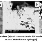
Concerning Ni-Si samples after the thermal cycling, in addition to open pores, the SEM image of the oxidized surface shows very stable silicon particles embedded in the composite coating (Figure 5a).
Figure 5: Micrographs of surface (a) and cross-section in BSE mode (b). Etched cross-section of Ni-Si after thermal cycling (c)
This observation proves the stability of those particles at the working temperature range.
However, in addition to black spots in the cross-section, corresponding to silicon particles (Figure 5 b), cracks and coaxial grains develop together with cycling due to stress generated in the material 39. The etching of Ni-Si reveals regular stripes in deep hollows (Figure 5c).
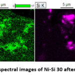
The observation of Si and O energy dispersive spectra indicates a good matching (Figure 6), which demonstrates the formation of silicon oxide onto silicon particles.
Figure 6: Energy dispersive spectral images of Ni-Si 30 after 23 cycles of heat treatment
Oxygen atoms diffuse through grain boundaries and oxidize preferentially silicon particles due to their chemical affinity. The Gibbs energy of the silicon oxidation (Δr Go(SiO2; 1500oC)=─598.312 kJ.mol–1) is more negative than that of nickel oxidation (ΔrGo(NiO2; 1500oC)= ─167.36 kJ.mol–1) according to the Ellingham diagram 40. Thus, Si and Ni are both involved in the oxidation process of Ni-Si films. Then, the consumption of oxygen, as well as the gain of mass for this coated sample becomes higher than that of others as observed in Figure 1.
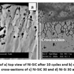
Regarding Ni-SiC films, the cross-sectional view of the thermally treated film after the 23rd cycle shows carbon (graphite) in the nickel matrix, especially at the grain boundaries (Figure 7a).
Figure 7: Micrographs of a) top view of Ni-SiC after 10 cycles and b) cross-section Ni-SiC 30 after 23 cycles. Etched cross-sections of c) Ni-SiC 30 and d) Ni-Si 30 after 23 thermal cycles
At temperatures above 320 °C, nickel dissolves silicon carbide particles, and forms nickel silicide while graphite is released in the bulk material 25, 41-43. However, silicide formation had not been observed in the experiments conducted here. Thus, the Ni oxide grain boundaries which are paths for nickel and oxygen ions (Ni2+, O2+) diffusion at high temperatures lower than 1000° C are effectively obstructed by carbon and the segregation of nickel atoms occurs 44,45. Since the outward diffusion of nickel is impeded. In addition, according to the Ellingham diagram oxygen diffusing inward is used for carbon monoxide and carbon dioxide formations rather than for nickel oxidation40. Thus, a lower rate of weight gain is obtained with the Ni-SiC coatings as shown in Figure 1.
The etching of the cross-section of composite coatings highlights the particular scale structures of Ni-SiC film. It shows a network of coaxial grains, while the Ni-Si 30 depicts regular stripes in deep hollows (Figure 5c and Figure 7 b, respectively). The main difference between Ni-Si and Ni-SiC coatings is the preferential and oriented oxidation of the particles, but also the different mechanical stress that each type of particle might induce into the Ni matrix during the thermal treatment. Indeed, the presence of refractory particles in the metal matrix prevents its thermal expansion generating additional stress. Additionally, with the same amount of particles (i.e. wt.1%), the stress generated by SiC particles is about four times higher than that produced by Si particles as the specific surface of SiC (i.e. 21.3 m2.g–1) is higher than that of Si (i.e. 5.7 m2.g–1) 46. Thus, it stands to reason that cracks originate from SiC particles as depicted in Figure. Thus, the Ni-SiC scale cracks into a stable network of islands partially insulated by carbon released, as discussed previously.
Electrochemical Impedance Spectroscopy (EIS)
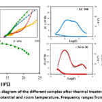
It is expected that during thermal treatment, and because of the oxidation process, the prepared coatings will generate different oxide layers with different compactness and chemical structure which will protect or not the steel specimen from the corrosive environment. Figure 8 shows the Nyquist and the Bode diagrams obtained with each sample in 100 mM KNO3 at open circuit potential (OCP). The insets in the Nyquist diagram (Figure 8) are an expanded view of the impedance data at high frequencies.
Figure 8: Nyquist impedance diagram of the different samples after thermal treatment measured in 100 mM KNO3 at open circuit potential and room temperature. Frequency ranges from 10 kHz to 10–2 Hz.
In Nyquist plots, XC100 and Ni-SiC seem to present only one semi-circle but Ni and Ni-Si samples exhibit a first semi-circle at high frequencies. However, the analysis of Bode diagrams clearly exhibits two maxima in angle evolution as a function of the frequency indicating that all samples polarized with two relaxation times. The second time constant is necessarily related to the oxide layer. Then, the Randles equivalent circuit is judiciously used to fit the experimental values present in Figure 9.
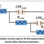
Figure 9: Equivalent circuit used to fit the experimental impedance results after thermal treatment.
In Figure 9, Rs is the uncompensated resistance of the solution, and Roxide and Rct are the charge-transfer resistance and the oxide resistance respectively. CPEdland CPEoxide are the so-called constant phase element (CPE) for the double-layer capacitance of the electrode and the generated oxide film. The solid lines representing the fitting curves are in good agreement with experimental records. Roxide and Rct values after the thermal oxidation are summarized in Table 2.
Table 2: Evolution of the charge transfer resistance of the sample before and after 21 cycles of thermal treatment.
Roxide (Ω)
Rct (KΩ)
XC100
164.2
1.92
Ni
57.76
6.87
Ni-Si
31.5
5.09
Ni-SiC
570.6
27.15
Rct is the highest for Ni-SiC i.e. 27.15 KΩ. This value is due to the unavailability of the Fermi gas but rather due to the scale made of the network of coaxial grains isolated among them as shown by microstructures. Since, the electrical conductivity of carbon; 61.103 S.m–1 is lower than that of nickel 14.106 S.m–1, the film resistance is increased by the graphite located in the grain boundaries. Therefore, the bulk resistance of the material and particularly the charge transfer resistance for Ni-SiC 30 composite coating is found to be the highest, as well as its efficiency to protect the steel XC 100 against high-temperature corrosion.
Contrary, stripes hallow of Ni-Si are disposed to electrical polarisation and the charge transfer resistance for this sample is lower, being 5.09 KΩ compared to Rct of Ni which is 6.87 KΩ. This corroborates the preferential oxidation of Si into SiO2 observed. Silicon particles act as an oxygen pump. Thus, fewer electrons from the conduction band of nickel are involved in interaction with oxygen. Ni-Si is so prevented from further oxidation. Concerning XC100, oxide scales of steels are well known to be non-adherent because of spallation. Insofar, as thermal cycling, new parts of the underlying XC 100 are directly exposed to the solution when the impedance experiment is performed. Thus, the non-oxidized underlying steel which is more conductive favours electrical polarisation and Rct decreases to 1.92. Likewise, oxide resistance Roxidevaluesfollow the same trend. The latter is in good agreement with the results observed in the gravimetric experiments.
Conclusion
The protection of the steel XC 100 against high-temperature corrosion due to butane/propane flame have been successfully undertaken employing nickel Ni and Ni-Si and Ni-SiC electrodeposited composite coatings loaded with about 1 wt. % silicon and silicon carbide particles. The results of gravimetric experiments indicated that coatings Ni and Ni-Si and Ni-SiC decrease the rate of weight gain by 13.33, 8, and 20 times respectively. The microstructures examination performed by SEM/EDS exhibit a Ni compact nickel oxide layer while Ni/SiC showed an oxide scale made of coaxial grains with carbon released at boundaries. Besides, the preferential oxidation of silicon into silicon oxide was observed for Ni-Si. Silicon particles inside act as an oxygen pump for this composite and the nickel matrix is prevent oxidation. The electrical parameters of charge transfer resistance and oxide resistance obtained by fitting the experimental values of electrochemical impedance spectroscopy have confirmed the trend of gravimetric evolutions.
Acknowledgment
The authors express their gratitude to Hubert Girault (LEPA/EPFL) for the opportunity given to me; an to Véronique Amstutz (LEPA/EPFL), Ludger Weber (EPFL, LMM), and Daniel Laub (CIME/EPFL) for their availability, enlightened discussions, and for their expert and kind help.
Conflict of interest
The authors declare no conflict of interest.
FundingSources
This work was financially supported by the “Swiss Government Excellence Scholarship” (No. 2012.067/Côte d’Ivoire/OP).
References
N. Bertrand, C. Desgranges, D. Poquillon, M. C. Lafont, and D. Monceau, “Iron Oxidation at Low Temperature (260–500 °C) in Air and the Effect of Water Vapor,” Oxid. Met., vol. 73, no. 1–2, pp. 139–162, Aug. 2009, doi: 10.1007/s11085-009-9171-0. CrossRef
P. Kofstad, High Temperature Corrosion. Elsevier Applied Science, 1988.
L. Marchetti et al., “Photoelectrochemical study of nickel base alloys oxide films formed at high temperature and high pressure water,” Electrochem. Acta, vol. 55, no. 19, pp. 5384–5392, 2010, doi: 10.1016/j.electacta.2010.04.063. CrossRef
E. Andrieu, R. Molins, H. Ghonem, and A. Pineau, “Intergranular crack tip oxidation mechanism in a nickel-based superalloy,” Mater. Sci. Engenineering, vol. A154, pp. 21–28, 1992. CrossRef
P. Caron, “High gamma Solvus New Generation Nickel-Based Superalloys for Single Crystal Turbine Blade Applications,” in Superalloys 2000, vol. 5, 2000, pp. 737–746. CrossRef
A. Machet, A. Galtayries, P. Marcus, P. Combrade, P. Jolivet, and P. Scott, “XPS study of oxides formed on nickel-base alloys in high-temperature and high-pressure water,” Surf. Interface Anal., vol. 34, pp. 197–200, 2002, doi: 10.1002/sia.1282. CrossRef
K. Kawagishi, H. Harada, A. Sato, A. Sato, and T. Kobayashi, “The Oxidation Properties of Fourth Generation Single-Crystal Nickel-Based Superalloys,” JOM, pp. 43–46, 2006. CrossRef
R. Peraldi, D. Monceau, B. Pieraggi, “Correlations between growth kinetics and microstructure for scales formed by high-temperature oxidation of pure nickel. II. Growth Kinetics,”Oxidation of Metals, vol. 58, no. 3-4, pp. 275–295, 2002. CrossRef
A. A. Moosa, S. J. Rothman, and L. J. Nowicki, “Effect of yttrium additions to nickel on the volume and grain boundary diffusion of Ni in the scale formed on the alloy,” Oxid. Met., vol. 24, no. 3–4, pp. 115–132, 1985. CrossRef
R. Herchl, N. Khoi, T. Homma, and W. Smeltzer, “Short-circuit diffusion in the growth of nickel oxide scales on nickel crystal faces,” Oxid. Met., vol. 4, no. 1, pp. 35–49, 1972. CrossRef
D. Caplan, M. J. Graham, and M. Cohen, “Effect of Cold Work on the Oxidation of Nickel at High Temperature.,” J. Electrochim. Soc., vol. 119, no. 9, pp. 1205–1215, 1972. CrossRef
L. E. Murr, E. Martinez, S. M. Gaytan, D. A. Ramirez, and B. I. Machado, “Microstructural and Mechanical Properties for a Nickel-Base Superalloy Fabricated by Electron Beam Melting,” Metall. Mater. Trans. A, vol. 42A, no. November, pp. 3491–3508, 2011, doi: 10.1007/s11661-011-0748-2. CrossRef
K. Yuan, R. Eriksson, R. Peng, X. Li, S. Johansson, and Y. Wang, “Modeling of the microstructural evolution and lifetime prediction of MCrAlX coatings on Nickel based superalloys in high temperature oxidation,” Surf. Coatings Technol., vol. 15, no. 232, pp. 204–215, 2013. CrossRef
R. Haugsrud, “On the high-temperature oxidation of Fe, Co, Ni and Cu-based alloys with addition of a less noble element,” Mater. Sci. Eng. A, vol. 298, no. 1–2, pp. 216–226, Jan. 2001, doi: 10.1016/S0921-5093(00)01315-0. CrossRef
E. B. Zaretsky, G. I. Kanel, S. V Razorenov, and K. Baumung, “Impact strength properties of nickel-based refractory superalloys at normal and elevated temperatures,” Intern. J. Impact Eng., vol. 31, pp. 41–54, 2005, doi: 10.1016/j.ijimpeng.2003.11.004. CrossRef
L. Zheng, M. Zhang, and J. Dong, “Oxidation behavior and mechanism of powder metallurgy Rene95 nickel based superalloy between 800 and 1000◦ C,” Appl. Surf. Sci., vol. 256, pp. 7510–7515, 2010, doi: 10.1016/j.apsusc.2010.05.098. CrossRef
G. Hochstetter, J. C. Chassaigne, and E. Andrieu, “Oxidation effects on the fatigue crack growth behaviour of alloy 718 at high temperature,” Acta Mater., vol. 45, no. 2, pp. 663–674, 1997. CrossRef
D. A. Woodford, “Gas phase embrittlement and time dependent cracking of nickel based superalloys,” Energy Mater., vol. 1, no. 1, pp. 59–79, 2006, doi: 10.1179/174892306X99679. CrossRef
Y. Zhang, X. Peng, and F. Wang, “Development and oxidation at 800 °C of a novel electrodeposited Ni–Cr nanocomposite film,” Mater. Lett., vol. 58, no. 6, pp. 1134–1138, Feb. 2004, doi: 10.1016/j.matlet.2003.09.006. CrossRef
G. A. Di Bari, “Electrodeposition of nickel,” in Modern Electroplating, 5th ed., M. Schlesinger and M. Paunovic, Eds. 2010, p. 95. CrossRef
F. H. Stott and D. J. Ashby, “The oxidation characteristics of electrodeposited nickel composites containing silicon carbide particles at high temperature,” Corros. Sci., vol. 18, pp. 183–198, 1978.
R. Mévrel, “State of the Art on High-temperature Corrosion-resistant Coatings,” Mater. Sci. Engenineering, vol. A 120, pp. 13–24, 1989. CrossRef
P. Fellner and P. K. Cong, “Ni-B and Ni-Si composite electrolytic coatings,” Surf. Coatings Technol., vol. 82, pp. 317–319, 1996. CrossRef
M. Backhaus-Ricoult, “Solid state reactions between silicon carbide and (Fe , Ni , Cr )-alloys : reaction paths , kinetics and morphology.,” Acta Met. mater., vol. 40, pp. s95-S103, 1992. CrossRef
T. C. Chou, A. Joshi, and J. Wadsworth, “Solid state reactions of SiC with Co, Ni, and Pt,” J. Mater. Res., vol. 6, no. 4, p. 800, 1991. CrossRef
L. Burzyńska, E. Rudnik, J. Koza, and L. Błaż, “Electrodeposition and heat treatment of nickel/silicon carbide composites,” Surf. Coatings Technol., vol. 202, no. 12, pp. 2545–2556, Mar. 2008, doi: 10.1016/j.surfcoat.2007.09.020. CrossRef
P. Nash and A. Nash, “The Ni-Si (Nickel-Silicon) system,” Bull. Alloy Phase Diagrams, vol. 8, no. 1, pp. 6–10, 1987. CrossRef
R. C. J. Schiepers, J. a. van Beek, F. J. J. van Loo, and G. de With, “The interaction between SiC and Ni, Fe, (Fe,Ni) and steel: Morphology and kinetics,” J. Eur. Ceram. Soc., vol. 11, no. 3, p. 212, Jan. 1993, doi: 10.1016/0955-2219(93)90090-E. CrossRef
A. Bächli, M.-A. Nicolet, L. Baud, C. Jaussaud, and R. Madar, “Nickel film on ( 001 ) SiC : Thermally induced reactions,” Mater. Sci. Eng. B, vol. 56, pp. 11–23, 1998. CrossRef
O. P. Watts, “Rapid Nickel Plating,” Trans. Am. Electrochem. Soc., vol. 29, p. 395, 1916.
D. M. K. Abro, P. J. M. R. Dablé, V. Amstutz, E. K. Kwa-koffi, and H. Girault, “Forced Electrocodeposition of Silica Particles into Nickel Matrix by Horizontal Impinging Jet Cell,” J. Mater. Sci. Chem. Eng., vol. 5, pp. 51–63, 2017, doi: 10.4236/msce.2017.52006. CrossRef
N. M. Marinov et al., “Aromatic and Polycyclic Aromatic Hydrocarbon Formation in a Laminar Premixed n-Butane Flame,” Combust. Flame, vol. 114, pp. 192–213, 1998, doi: doi.org/10.1016/S0010-2180(97)00275-7. CrossRef
N. Birks and G. H. Meier, Introduction to High Temperature Oxidation of Metals, Edward Arn. London, 1983.
A. S. Khanna, Introduction to High Temperature Oxidation and Corrosion., Illustrée. London, 2002.
R. Y. Chen and W. Y. D. Yuen, “Review of the High-Temperature Oxidation of Iron and Carbon Steels in Air or Oxygen.,” Oxid. Met., vol. 59, no. 5/6, pp. 433–468, 2003.
R. H. Bricknell and D. A. Woodford, “The mechanism of cavity formation during high temperature oxidation of nickel .,” Acta Metall., vol. 30, pp. 257–264, 1982. CrossRef
N. B. Pilling and R. E. Bedworth, “The Oxidation of Metals at High Temperatures,” J. Inst. Met., vol. 29, pp. 529–591, 1923.
A. Atkinson and W. D. Smart, “Transport of nickel and oxygen during the oxidation of nickel and dilute nickel/chromium alloy.,” J. Electrochem. Soc., vol. 135, no. 11, pp. 2886–2893, 1988. CrossRef
P. Kofstad, “On the formation of porosity and microchannels in growing scales.,” Oxid. Met., vol. 24, no. 5–6, pp. 265–276, 1985. CrossRef
M. Olette and M. F. Ancey-Moret, “Variation de l’énergie libre de formation des oxydes et des nitrures avec la température.,” Rev. Métallurgie, vol. 60, no. 6, pp. 569–581, 1963. CrossRef
M. Backhaus-Ricoult, “Solid state reactions between sic and various transition metals,” Berichte der Bunsengesellschaft für Phys. Chemie, vol. 93, no. 11, pp. 1277–1281, 1989. CrossRef
M. Ghouse, “Influence of heat treatment on the bond strength of codeposited Ni-SiC composite coating,” Surf. Technol., vol. 21, pp. 193–200, 1984. CrossRef
T. Fujimura and S.-I. Tanaka, “In-situ high temperature X-ray diffraction study of Ni/SiC interface reactions,” J. Mater. Sci., vol. 4, p. 237, 1999.
W. W. Smeltzer, “The Influence of Short-Circuit Grain Boundary Diffusion on the Growth of Oxide Layers on Metals.,” Mater. Sci. Forum, vol. 29, pp. 151–172, 1988. CrossRef
A. Atkinson, “Transport processes during the growth of oxide films at elevated temperature,” Rev. Mod. Phys., vol. 57, no. 2, pp. 437–470, Apr. 1985, doi: 10.1103/RevModPhys.57.437. CrossRef
D. M. K. Abro et al., “Characterization of Surface State of Inert Particles : Case of Si and SiC,” J. Miner. Mater. Charact. Eng., vol. 3, no. January, pp. 1–11, 2016.

 , Collette A. Djassou1, Yao J. Adjoumani2