Dinesh Bejjanki , Vrushabh Dharmik, Uday Bhaskar Babu Gara and Sampath Kumar Puttapati*
Department of Chemical Engineering, National Institute of Technology, Warangal, Telangana, India.
Corresponding Author E-mail:pskr@nitw.ac.in
DOI : http://dx.doi.org/10.13005/msri/200304
Article Publishing History
Article Received on : 07 Dec 23
Article Accepted on : 04 Jan 2024
Article Published : 11 Jan 2024
Plagiarism Check: Yes
Reviewed by: Dr. Md Abdul Majed Patwary
Second Review by: Dr. Pachuru.Mohan Babu
Final Approval by: Dr. Roberto Aceved
Article Metrics
ABSTRACT:
Currently, lithium-ion batteries have the highest energy density; hence naturally, this chemistry is the most promising solution for high-density energy storage. This means the commercially used anode material, that is, graphite with a theoretical capacity of 372 mAh/g, needs to be improved; hence the implementation of more capacity material is needed. In regard, silicon is the best alternative available for this with ~4200 mAh/g theoretical capacity. In this work an industrially scalable procedure using ultrasonication followed shear mixer to synthesize a composite of ball-milled silicon with exfoliated graphite for the anode material in lithium-ion batteries. The material is characterized using X-ray diffraction for crystallite information, and scanning electron microscopy shows the composite visuals with X-ray photoelectron spectroscopy to indicate bonding details in the composite, along with half coin-cell tested for18 cycles with a capacity of 222.48 mAh/g and columbic efficiency of 97.86%. Hence the silicon/exfoliated graphite composite using 2 step ultrasonic and shear process can be economical and scalable.
KEYWORDS:
Anode; Active material; Capacity; Li-ion battery; Silicon
Copy the following to cite this article:
Bejjanki D, Dharmik V, Gara U. B. B, Puttapati S. K. Ultrasonic-Assisted Synthesis of Silicon/Exfoliated-Graphite Nanocomposite as Anode Material for Lithium-Ion Batteries. Mat. Sci. Res. India;20(3).
|
Copy the following to cite this URL:
Bejjanki D, Dharmik V, Gara U. B. B, Puttapati S. K. Ultrasonic-Assisted Synthesis of Silicon/Exfoliated-Graphite Nanocomposite as Anode Material for Lithium-Ion Batteries. Mat. Sci. Res. India;20(3). Available from: https://bit.ly/4aPoMvn
|
Introduction
To tackle the problem of pollution, increase and rapidly depleting fossil fuel deposits, transfer from traditional energy sources to renewable energy sources such as solar, wind and tidal energy is priority. In the same efforts the world has turned towards the most efficient energy form that is electricity. Now to be able to produce and use this electricity as per requirement in applications such as electric vehicles and ever becoming powerful electronics bigger, lighter and more compact batteries with higher capacities are required. Consequently, the demand for high-capacity batteries is increasing even more rapidly.
Hence need of bigger and better batteries is more now, than ever. Whereas, the active material in the anode of a lithium-ion battery which is responsible for the energy storage capacity, Graphite, has theoretical capacity of only 372 mAh/g1 which is not enough as there is always an upper constrain on a battery size and weight. Also, for the graphite whole market is dependent upon very few selective countries, such as, China which produced about 72% of total graphite in 2021. Hence, the market is in need of a more widely available, cheaper and more capable alternative for graphite. There are various alternatives, such as Tin with theoretical capacity of 990 mAh/g (~2.6× that of graphite), Aluminum with 2235 mAh/g (~6× that of graphite) theoretical capacity2 but globally accepted and being preferably studied of such an alternatives is silicon with maximum theoretical capacity of 4200 mAh/g, which is about 11× that of graphite and is the second most abundant element in earth’s crust mostly in the form of its oxide, Silica (SiO2). Now as the silicon anode is charging, after complete lithiation of silicon, a complex of silicon and lithium forms Li22Si15 due to which diamond cubic closed-pack silicon crystal suffers a massive expansion of about 400%3,4 of its original volume hence rendering silicon bonds to experience excessive strain and in case of bigger particles, pulverize resulting in losing the contact with the current collector, that is cell end-up losing active anode material and hence the cycling capacity. Other major hindrance is Solid Electrolyte Interface (SEI) formation5, it forms during the first electrochemical reactions begin to occur. On the surface of the anode some of the lithium ions form passivation layer6 which in a way forms a lithium leakage prevention layer and is beneficial but at the cost of electrolyte. Hence during the continuous cycling, the silicon crystals pulverize and new active surface is exposed to the electrolyte causing more SEI formation and consequently resulting in more loss of active anode material as well as electrolyte7. Hence reducing the cyclability of the cell.
To solve this problem, one obvious solution could be to reduce the particle size, as Jin et. al.8 discovered that, the smaller particle size will result in more SEI formation due to higher surface area and, on the other hand reduced mechanical degradation because of the stabilized SEI. Hence there is an optimal particle size where particles above 150 nm suffer fracture in particles and in subsequently pulverization9. By modifying the geometry such as, silicon nanowires10 or nanotubes with radial dimension being ~50-60 nm and keeping lateral dimension larger, the tensile hoop strain is reduced in radial direction hence reducing pulverization along with keeping very much intact connection with current collector after many cycles and practically 1D path for electrons to flow hence further reduced electron loss11. Although to synthesize these modified electrodes, processes like vapour-liquid-solid templet-free growth method12, metal assisted chemical etching (MACE), electrospining and chemical vapour deposition such specialized, unsuitable for mass market techniques are used. One of the more interesting solutions could be making the silicon electrode by creating silicon microstructures, done by sternad et. al.13 which showed promising results but again the procedure used was deep reactive ion etching, which would require whole new process development and cannot be just retrofitted in the existing cell manufacturing process. One other solution could be making silicon particles porous so most of the volume for expansion after lithiation could be accommodated inside the pore volumes itself such as done by, li et. al.14 using electrochemical etching of silicon wafer, wang et. al.15 used magnesiothermic reduction reaction to convert silica to porous silicon in inert atmosphere, Zhang et. al.16 did rochow Reaction where carbon deposited porous silicon is the by-product and, Lai et. al.17 studied metallothermic reduction reaction on silica using Mg, Al, Ca as the reducing agents in high temperature inert atmosphere. Although all these articles report excellent performances, these methods required either inert atmosphere at very high temperature or there is a considerable loss of active silicon material through etching. Other solution could be a composite, such as, silicon particles covered by layered material such as graphene or few-layered graphite which prevents direct contact of active material surface with electrolyte and restrict the excessive SEI formation also while holding the silicon particles. Chen et. al.18 did ultrasonication of graphene oxide and silicon nanoparticles (<80nm), Xiang et. al.19 mechanically blended the mixture of reduced-graphene oxide and silicon nanoparticles, Liu et. al.20 used CTAB surfactant solution to exfoliate pristine graphite flex and intercalate 100nm silicon particles via bath sonication and, Wang et. al.21 also did ultrasonication of graphene oxide and 3-80 nm silicon particles. All these methods demonstrate good cyclic performance of the coin-cell, but the silicon being used is <100 nm which is expensive to synthesize and obtain along with few procedures being multi-step with exclusive chemical usage making these procedures non-cost effective22, 23. Also processes where graphene oxide or reduced-graphene oxides are used have an additional step of reducing graphene oxide using chemicals like hydrazine which is not easy to operate and costly to scale-up.
Herein we have used materials that are easy to obtain, either by procuring or producing with industrially viable procedures. Micro silicon of 1-10 μm size can be obtained using Ball milling (hence ball-milled silicon) or other physical attrition top-down processes24, Exfoliated graphite which are precursors of many graphite-based composites, are easily available in market at reasonable prices. For solvent we have used, DI water, Propane-2-ol and Sodium Cholate surfactant, all of which are used in number of processes hence easy to obtain. Since no chemical reaction is intended hence, simple Shear mixing operation and drying are the two steps of composite synthesis process. After synthesizing the composite essential characterization and coin-cell testing has been done to observe the properties and understand the workability of the composite respectively.
Experimental
Preparation of silicon-graphite composite
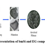
As demonstrated in Fig. 1, a solvent was prepared by adding Isopropyl alcohol in water making a 5.8 vol% alcohol-water solution. This solution has equal surface energy as the graphite sheets25, 26, 27. In this 200mL of solution 0.15g of Cholic acid sodium salt was added. In this solution, 0.8g (20 wt%) of as-bought exfoliated graphite was added and shear mixing was started at 6000 RPM. After a while when the solvent and EG solution becomes uniform 3.2g (80 wt%) of ball-milled silicon was added and the whole solution was then shear mixed in an ice bath for 180 min. After the completion of the mixing the solution was filtered and this filtrate was dried in oven at 150°C overnight.
Material characterization and analysis
To get a primary sense of the material composition and its crystalline nature, the X-ray diffraction spectroscopy (XRD) pattern of the composite was taken using XRD PANalytical, X’Pert-PRO MPD using Cu K(α) radiation. The composite is essentially an engineered unreacted material mixture, hence to properly understand the effect of and changes due to the procedure we need to visualize the material; hence Scanning Electron microscopy (SEM) images were obtained with the help of TESCAN, VEGA3 LMU. Along with the SEM images a Energy-dispersive X-ray Spectroscopy data was also obtained. Understanding the material nature in terms of the bonds between different elements and proportions is very important while characterizing a material. Hence X-ray Photoelectron Spectroscopy taken with AXIS SUPRA+, Kratos and Fourier Transform Infrared Spectroscopy done with LAMBDA 365 UV/Vis Spectrophotometer data was generated. And at the end to test the applicability of the composite half coin-cell tests were done.
Results and Discussion
X-ray Diffraction Spectroscopy
Fig. 2 shows the comparative XRD plot of the final product with individual silicon and graphite reference plots. First conclusion to make is both silicon and exfoliated graphite are crystalline. And as we can see, all the essential peaks of the silicon and graphite are present. The Graphite peaks are, G(002) at 26.6° and one minor peak G(004) at 54.4°; out of which only G(002) peak is present. With respect to silicon, three main peaks are, Si (111) at 28.7°, Si(220) at 47.5° & Si(311) at 56.3° which all are present in Si/G composite plot. Using
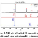 |
Figure 2: XRD plot (a) bmSi & EG composite plot
(b) silicon reference plot (c) graphite reference plot
Click here to View Figure
|
scherrer’s formula the planer spacing and lattice parameter calculation for this XRD is shown in the Table 1. Comparing the obtained peaks and the reference peaks, as the obtained peaks are slightly on higher 2θ than the reference peaks, we can conclude that the crystals of the final composite material is in compressive strain. Also, the base of the peaks in the plot are slightly wider compared to corresponding reference peaks, which indicates that the silicon and graphite particles are smaller in size. But the spread is not as much to indicate the particles being in nanoscale.
Table 1: Planner Spacing and Lattice Parameter calculations
|
|
2θ
|
FWHM
|
Planner Spacing (nm)
|
Lattice Parameter (nm)
|
|
G (002)
|
26.72118
|
0.30931
|
46.10975
|
92.21949
|
|
Si (111)
|
28.64597
|
0.15605
|
91.77416
|
158.95750
|
|
Si (220)
|
47.49728
|
0.20775
|
72.97197
|
206.39590
|
|
Si (311)
|
56.29874
|
0.26238
|
59.98032
|
198.93222
|
Scanning Electron Microscopy and Energy-dispersive X-ray Spectroscopy
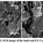
SEM works on a similar principle of reflection of light microscopy, except the reflection of electron, they may be secondary electrons (conventionally electrons with <50eV energy) or backscattered electrons (electrons with >50eV energy). The greater number of detected electrons, the brighter the part (or pixel) of the image also the higher the atomic number of the material, the greater number of detectable electrons. Now as we have established an understanding of SEM working principle, the Fig. 3, shows the morphology of the composite. In the SEM images we can clearly distinguish between the large, flat and darker graphite sheets and small, irregular, brighter and pebble shaped silicon particles. Even exfoliated graphite being only 20 weight% in the composite due to its larger size, most of the ball-milled silicon is covered under these graphite sheets. In the Fig. 3(b) in the highlighted region, we can see some small (equivalent is size of other distinguishable silicon particles) regions elevated in brightness, these could indicate the thin layer coverage of exfoliated graphite sheet
Over the ball-milled silicon particles. In the more usual case where the silicon particles of this scale and shape would easily pulverize and demolish due to high hoop strain induced by charge-discharge cycling and excessive SEI formation. Resulting in arrested working of the anode and hence the coin-cell. But due to the covering provided by the exfoliated graphite sheets, even the pulverized particles of ball-milled silicon are retained by the electrode and by preventing the direct contact of silicon active surface and electrolyte the excessive SEI formation is also protected.
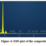
Here, Fig. 4 show the EDS plot, which is based on Auger electron detection (complimentary to SEM). Rightfully indicates approximate amount of ball-milled silicon with respect to the exfoliated graphite and also indicates the impurities present in the composite, such as oxygen, aluminium and iron.
X-ray Photoelectron Spectroscopy
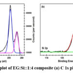
Understanding the material in terms of the bonds formed in between the elements and their proportions is really important while characterizing a material to understand the performance and/or phenomenon occurring during the application testing. Hence, a surface sensitive analytical technique, XPS which is based on the measurement of kinetic energy of the ejected Auger electrons after bombardment of a high energy x-ray beams (typically Mg kα or Al kα) to calculate the Binding Energy (BE) of the ejected electrons which varies with the environment of the atom is ejected28. The Fig. 5(a) shows the spectrum of C 1s, out of which the the blue peak with BE ~ 284.44 eV indicates pristine carbon i.e., unreacted exfoliated graphite itself. Whereas the purple peak with BE ~ 282 eV carbide peak, which indicates some kind of inter-molecular interaction is occurring between ball-milled silicon and exfoliated graphite and/or carbon present in the Sodium Cholate surfactant. The Fig. 5(b) shows the spectrum of Si 2p, in which the green peak with BE ~ 96.7 eV which indicated towards pristine ball-milled silicon and the red peak with BE ~ 100.12 eV which again indicates the carbide bond which reinforces the observation with by C 1s peak. From this observation we can conclude that, silicon is partially interacting with either exfoliated graphite or carbon present in the surfactant. But since there is not enough energy for exfoliated graphite and silicon to react the latter is more likely. From the area under both the blue and purple peaks shows that about 69.09% of the carbon is unreacted and from the area under the green and red peaks shows about 41.03% silicon is pristine. Other than this there is no significant evidence of presence of the impurities unlike in EDS.
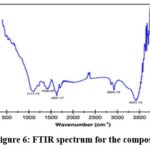
Fourier Transform Infrared Spectroscopy
To analyse the composite more FTIR data was obtained. The spectrum shown in Fig. 6 presents, several characteristic peaks, such as, C-O (1117.74 cm-1) which represents the secondary alcohol bond, O-H (1436.42 cm-1) which is bending carboxylic group which probably originated from the surfactant that was used in the solvent. C=C (1631.17 cm-1) which shows conjugate alkene bonds and C-H (2924 cm-1) which shows alkane, both of which could be the result of modification of few graphite bonds and the O-H (3431.14 cm-1) which indicated intermolecular bond29,30.
Coin-Cell Testing
The most important test for a lithium-ion battery material is the coin-cell test. The name half coin-cell indicates that, the performing electrode is the electrode fabricated with the composite material to be tested and the other electrode (or reference electrode) is the pure lithium metal electrode. To cast the electrode, a blend of the composite of bmSi and EG was taken as 94.5 wt%, Carboxymethyl cellulose (CMC) was taken as 1.5 wt% and Styrene-butadiene rubber (CBR) was taken as 1.5 wt% both of the latter functions as a binder31,32. Since exfoliated graphite is present in the component there is no need of conductive material. This mix was turned into an ink by adding appropriate amount of N-methyl-2-pyrrolidone (NMP). This ink was then applied on a copper foil and with the help of the doctor’s Blade the film was made uniform of the thickness of 1mm. Then is electrode was placed on a hot-plate at 85°C temperature for about 2-3 min to evaporate all of the solvent NMP.
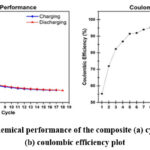 |
Figure 7: Electrochemical performance of the composite (a) cycling capacity plot (b) coulombic efficiency plot
Click here to View Figure
|
Then the 12mm electrodes were punched through this film. Then these electrodes were transferred to an glove-box with Ar atmosphere and coin cell was fabricated with counter electrode being pure lithium sheet33. Fig. 7(a) shows the cycling performance of the composite in half coin-cell testing and Fig. 7(b) shows the coulombic Efficiency (CE). The first discharge capacity came out to be 1578.57 mAh/g and first charge capacity being 871.89 mAh/g which indicates 55.23% initial coulombic efficiency. This capacity drops between 1st discharge and 1st charge is due to the formation cycle, i.e., during this cycle complete lithiation takes place, some of the parts and gaps of particles are saturated with lithium after lithiation and lose capacity permanently and most of the capacity loss is due to SEI formation. Almost all of the lost capacity due to formation cycle is permanently lost, because of these irreversible effects. And the 2nd cycle discharge capacity is 833.48 mAh/g. In the 5th cycle itself the CE crosses 90% and the 18th cycle capacity is 222.48 mAh/g with 97.85% CE. Fig. 8 shows the Charge-Discharge profile for all 18 cycles. Since there is no literature which deals with this size scale and easy to
Obtain silicon the capacity shown by the mentioned composite is appreciable since the expected stability of this type of silicon is negligible.
Conclusion
We established the research gaps in the literature and identified that out of all the different ideas and solutions, there was either a complex multi-stage process or very high temperature reaction in neutral environment and with speciality chemical requirement or a process where precursors are economically not viable for scaling. Hence the implementation of a composite made of simply ball-milled silicon and easily market-available exfoliated graphite in one-step shear mixing process can be economical and scaled easily. The first discharge capacity came out to be 1578.57 mAh/g and first charge capacity being 871.89 mAh/g which indicates 55.23% initial coulombic efficiency. The performance obtained from the composite is nowhere perfect or extraordinary but due to implementation of very simple procedure and cheaply available raw material, this solution holds key for many low-capacity needed applications, such as UPS, stationary power back-ups or energy storage infrastructures, instead of using lead-acid battery if such silicon batteries are used the working capacity can be increased drastically without requiring too much of excess investment.
Acknowledgment
The authors acknowledge, Dr. Venkat Ramana Gedela, Nanospan India Pvt. Ltd., Hyderabad, for giving valuable suggestions and support for this work.
Conflict of Interest
The research work supported by the NIT Warangal and authors are the principle investigator of the grants. The authors declare there are no conflicts of interest related to this work.
Funding source
NIT Warangal for providing the grant, RSM-P1112.
Reference
- Nitta, N., Wu, F., Lee, J.T., Yushin, G. Li-Ion Battery Materials: Present and Future. Mater. Today, 18, 252–264 (2015).
CrossRef - Mukhopadhyay, A. Sheldon, B.W. Deformation and Stress in Electrode Materials for Li-Ion Batteries. Prog. Mater. Sci., 63, 58–116 (2014)
CrossRef - Wang, Q, Zhu, M., Chen, G., Dudko, N. Li, Y. Liu, H. Shi, L. Wu, G. Zhang, D. High-Performance Microsized Si Anodes for Lithium-Ion Batteries: Insights into the Polymer Configuration Conversion Mechanism. Adv. Mater. 34, 1–13 (2022)
CrossRef - Malkowski, T.F. Yang, Z. Sacci, R.L. Trask, S.E. Rodrigues, M.T.F. Bloom, I.D. Veith, G.M. Evaluating the Roles of Electrolyte Components on the Passivation of Silicon Anodes. J. Power Sources, 523, 231021 (2022)
CrossRef - Piper, D.M. Evans, T. Leung, K. Watkins, T. Olson, J. Kim, S.C. Han, S.S. Bhat, V. Oh, K.H. Buttry, D.A. et al. Stable Silicon-Ionic Liquid Interface for next-Generation Lithium-Ion Batteries. Nat. Commun. 6, 1–10 (2015)
CrossRef - Kong, F. Kostecki, R. Nadeau, G. Song, X. Zaghib, K. Kinoshita, K. McLarnon, In Situ Studies of SEI Formation. J. Power Sources 97–98, 58–66 (2001)
CrossRef - Maurya Gyanprakash D, Chandresh Kumar Rastogi, Investigation of silicon nanoparticle size on specific capacity of Li-ion battery via electrochemical impedance spectroscopy. J. Electroanal. Chem. 931, 117176 (2023)
CrossRef - Jin, M.Y. Guo, K. Xiao, X. Verbrugge, M.W. Gao, H. Sheldon, B.W. Optimum Particle Size in Silicon Electrodes Dictated by Chemomechanical Deformation of the SEI. Adv. Funct. Mater. 31, 1–11 (2021)
CrossRef - Liu, X.H. Zhong, L. Huang, S. Mao, S.X. Zhu, T. Huang, J.Y. Size-Dependent Fracture of Silicon. ACS Nano, 6, 1522–1531, (2012)
CrossRef - Miao, F. Miao, R. Wu, W. Cong, W. Zang, Y. Tao, B. A Stable Hybrid Anode of Graphene/Silicon Nanowires Array for High Performance Lithium-Ion Battery. Mater. Lett. 228, 262–265 (2018)
CrossRef - Wu, H. Chan, G. Choi, J.W. Ryu, I. Yao, Y. Mcdowell, M.T. Lee, S.W. Jackson, A. Yang, Y. Hu, L. et al. Stable Cycling of Double-Walled Silicon Nanotube Battery Anodes through Solid-Electrolyte Interphase Control. Nat. Nanotechnol 7, 310–315 (2012)
CrossRef - Chan, C.K. Peng, H. Liu, G. McIlwrath, K. Zhang, X.F. Huggins, R.A. Cui, Y. High-Performance Lithium Battery Anodes Using Silicon Nanowires. Nat. Nanotechnol, 3, 31–35 (2008)
CrossRef - Sternad, M. Forster, M. Wilkening, M. The Microstructure Matters: Breaking down the Barriers with Single Crystalline Silicon as Negative Electrode in Li-Ion Batteries. Sci. Rep, 6, 2–9 (2016)
CrossRef - Li, X. Gu, M. Hu, S. Kennard, R. Yan, P. Chen, X. Wang, C. Sailor, M.J. Zhang, J.G. Liu, J. Mesoporous Silicon Sponge as an Anti-Pulverization Structure for High-Performance Lithium-Ion Battery Anodes. Nat. Commun,5, 4105 (2014)
CrossRef - Wang, W. Favors, Z. Ionescu, R. Ye, R. Bay, H.H. Ozkan, M. Ozkan, C.S. Monodisperse Porous Silicon Spheres as Anode Materials for Lithium Ion Batteries. Sci. Rep, 5, 2–7 (2015)
CrossRef - Zhang, Z. Wang, Y. Ren, W. Tan, Q. Chen, Y. Li, H. Zhong, Z. Su, F. Scalable Synthesis of Interconnected Porous Silicon/Carbon Composites by the Rochow Reaction as High-Performance Anodes of Lithium Ion Batteries. Angew. Chemie – Int. Ed. 53, 5165–5169 (2014)
CrossRef - Lai, Y. Thompson, J.R. Dasog, M. Metallothermic Reduction of Silica Nanoparticles to Porous Silicon for Drug Delivery Using New and Existing Reductants. Chem. – A Eur. J. 24, 7913–7920 (2018)
- Chen, Y. Zhang, X. Tian, Y. Zhao, X. Synthesis and Characterization of Silicon Nanoparticles Inserted into Graphene Sheets as High Performance Anode Material for Lithium Ion Batteries. J. Nanomater. 2014 1-6 (2014)
CrossRef - Xiang, H. Zhang, K. Ji, G. Lee, J.Y. Zou, C. Chen, X. Wu, J. Graphene/Nanosized Silicon Composites for Lithium Battery Anodes with Improved Cycling Stability. Carbon N. Y. 49, 1787–1796, (2011)
CrossRef - Liu, H. Shen, Z. Liang, S. Liu, L. Yi, M. Zhang, X. Ma, S. One-Step: In Situ Preparation of Liquid-Exfoliated Pristine Graphene/Si Composites: Towards Practical Anodes for Commercial Lithium-Ion Batteries. New J. Chem. 40, 7053–7060 (2016)
CrossRef - Wang, J.Z. Zhong, C. Chou, S.L. Liu, H.K. Flexible Free-Standing Graphene-Silicon Composite Film for Lithium-Ion Batteries. Electrochem. commun. 12, 1467–1470 (2010)
CrossRef - H. Li, H. Li, Y. Lai, Z. Yang, Q. Yang, Y. Liu, Z. Zheng, Y. Liu, Y. Sun, B. Zhong, Z. Wu and X. Guo, Revisiting the Preparation Progress of Nano-Structured Si Anodes toward Industrial Application from the Perspective of Cost and Scalability Adv. Energy Mater., 12, 1–25 (2022).
CrossRef - Z. Bitew, M. Tesemma, Y. Beyene and M. Amare, nano-structured silicon and silicon based composites as anode materials for lithium ion batteries: recent progress and perspectives. Sustain. Energy Fuels, 6, 1014–1050 (2022)
CrossRef - Zhu, X. Cai, X. Zhang, S. Wang, L. Cui, X. The Impact of Ball Milling Process Parameters on the Preparation of Nano Silicon Powder. Integr. Ferroelectr. 217, 255–264 (2021)
CrossRef - Park, J.-G. Lee, S.-H. Ryu, J.-S. Hong, Y.-K.; Kim, T.-G. Busnaina, A.A. Interfacial and Electrokinetic Characterization of IPA Solutions Related to Semiconductor Wafer Drying and Cleaning. J. Electrochem. Soc. 153, G811 (2006)
CrossRef - Messmer, C. Bilello, J.C. The Surface Energy of Si, GaAs, and GaP. J. Appl. Phys. 52, 4623–4629 (1981)
CrossRef - Kozbial, A. Li, Z. Conaway, C. McGinley, R. Dhingra, S. Vahdat, V. Zhou, F. Durso, B. Liu, H. Li, L. Study on the Surface Energy of Graphene by Contact Angle Measurements. Langmuir 30, 8598–8606 (2014)
CrossRef - Wang, H. Nadimpalli, S.P.V. henoy, V.B. Inelastic Shape Changes of Silicon Particles and Stress Evolution at Binder/Particle Interface in a Composite Electrode during Lithiation/Delithiation Cycling. Extrem. Mech. Lett. 9, 430–438 (2016)
CrossRef - Pharr, M. Suo, Z. Vlassak, J.J. Variation of Stress with Charging Rate Due to Strain-Rate Sensitivity of Silicon Electrodes of Li-Ion Batteries. J. Power Sources, 270, 569–575 (2014)
CrossRef - Stevie, F.A. Donley, C.L. Introduction to X-Ray Photoelectron Spectroscopy. J. Vac. Sci. Technol. A Vacuum, Surfaces, Film. 38, 063204 (2020)
CrossRef - Su, M. Wang, Z. Guo, H. Li, X. Huang, S. Xiao, W. Gan, L. Enhancement of the Cyclability of a Si/Graphite@Graphene Composite as Anode for Lithium-Ion Batteries. Electrochim. Acta 116, 230–236 (2014)
CrossRef - Liang, Y. Wu, D. Feng, X. Müllen, K. Dispersion of Graphene Sheets in Organic Solvent Supported by Ionic Interactions. Adv. Mater. 21, 1679–1683 (2009)
CrossRef - Li, J. Lewis, R.B. Dahn, J.R. Sodium Carboxymethyl Cellulose. Electrochem. Solid-State Lett. 10, 20–23 (2007).
CrossRef

This work is licensed under a Creative Commons Attribution 4.0 International License.